Touch screen and manufacture method thereof
A production method and touch screen technology, applied in the direction of instruments, electrical digital data processing, data processing input/output process, etc., can solve the problems of hindering light transmission, thick resistive touch screen, low transmittance of resistive touch screen, etc., to achieve easy Multi-touch, enhanced sensitivity, ultra-thin effect
- Summary
- Abstract
- Description
- Claims
- Application Information
AI Technical Summary
Problems solved by technology
Method used
Image
Examples
Embodiment 1
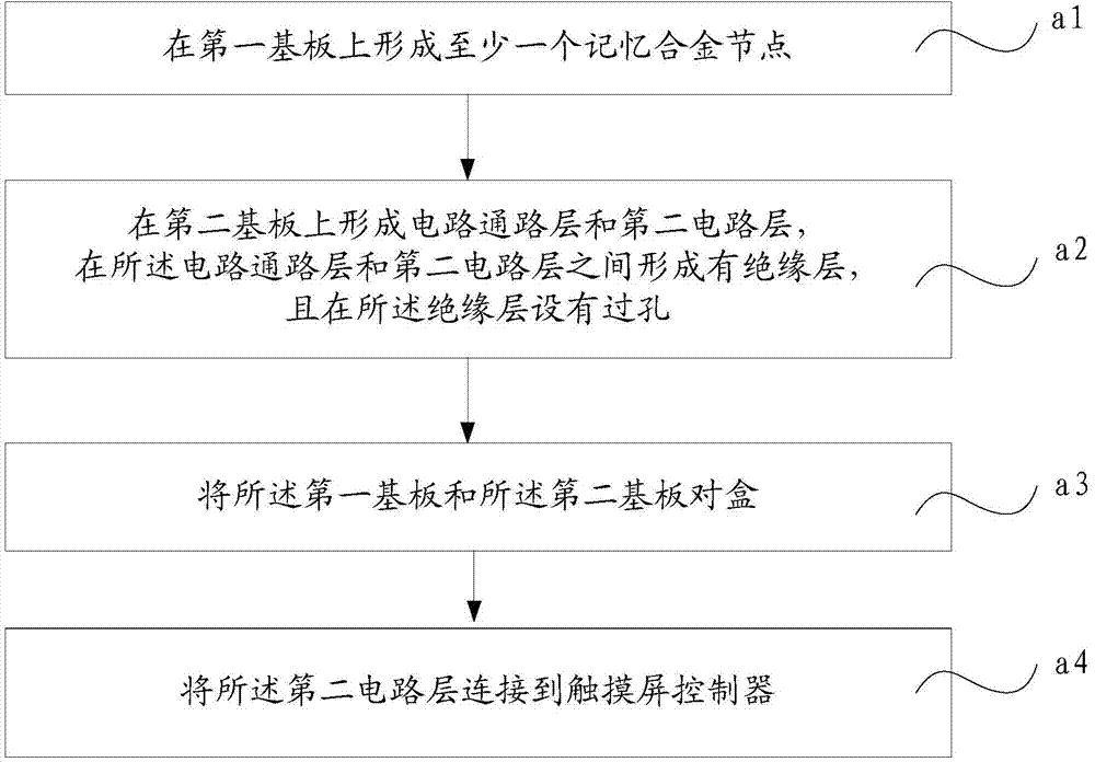
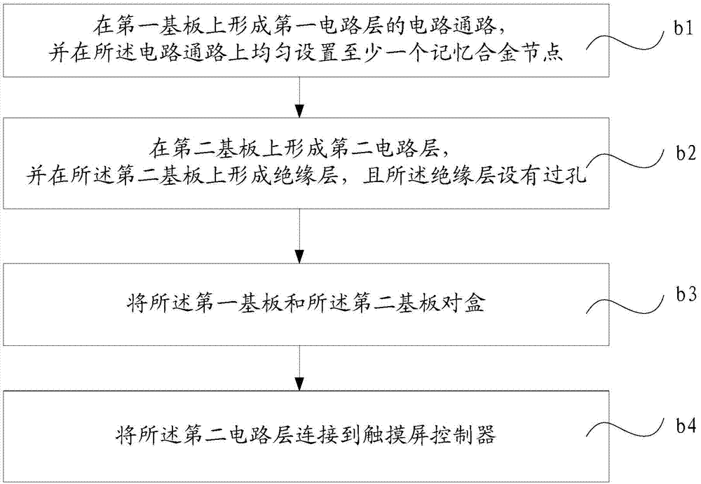
[0045] Such as figure 2 As shown, the touch screen provided in this embodiment includes a first substrate 01 and a second substrate 02 oppositely arranged and a touch screen controller, and a first circuit layer is formed between the first substrate 01 and the second substrate 02 and a second circuit layer 15, and an insulating layer 16 is formed between the first circuit layer and the second circuit layer 15;
[0046] The first circuit layer is used to sense the touch of external force, and the second circuit layer is used to transmit the signal of whether the touch point is touched by external force to the touch screen controller;
[0047]The first circuit layer includes at least one memory alloy node 12, and a circuit path 11 for supplying power to the at least one memory alloy node 12; in order to more clearly show the connection between the first circuit layer and the second circuit layer 15 The connection relationship, in the illustration, only the circuit connection o...
Embodiment 2
[0054] Such as Figure 5 As shown, the touch screen provided in this embodiment provides another implementation solution for the circuit design of the first circuit layer and the second circuit layer, and other designs are similar to the implementation solution of the first embodiment, and will not be repeated here.
[0055] In this embodiment, the circuit path in the first circuit layer is Figure 6 The mesh structure shown, with no connections between line ends at each mesh node. A memory alloy node 12 is provided at each grid node, and the memory alloy node 12 is fixed on the first substrate 01 . An insulating layer 16 is provided between the first circuit layer and the second circuit layer 15, and a via hole 14 filled with ITO is provided on the insulating layer 16, and the via hole 14 is provided at the memory alloy node 12 directly below and in contact with the memory alloy node 12, and there is no electrical connection with all wire ends at the grid node.
[0056] Su...
Embodiment 3
[0059] Such as Figure 7 As shown, the touch screen provided in this embodiment includes a first substrate 01 and a second substrate 02 oppositely arranged and a touch screen controller, and a first circuit layer is formed between the first substrate 01 and the second substrate 02 and a second circuit layer 15, and an insulating layer 16 is formed between the first circuit layer and the second circuit layer 15;
[0060] The first circuit layer includes at least one memory alloy node 12, and a circuit path 11 for powering the at least one memory alloy node 12; the second circuit layer 15 includes at least one wire connected to the touch screen controller , and each wire corresponds to a memory alloy node 12, so that the touch screen controller can detect the connection status between each memory alloy 12 and its corresponding wire.
[0061] Among them, in order to better sense the change of external force on the touch screen, soft glass is selected as the first substrate 01; i...
PUM
 Abstract
Description
Claims
Application Information
 - R&D
- Intellectual Property
- Life Sciences
- Materials
- Tech Scout
- Unparalleled Data Quality
- Higher Quality Content
- 60% Fewer Hallucinations
Browse by: Latest US Patents, China's latest patents, Technical Efficacy Thesaurus, Application Domain, Technology Topic, Popular Technical Reports.
© 2025 PatSnap. All rights reserved.Legal|Privacy policy|Modern Slavery Act Transparency Statement|Sitemap|About US| Contact US: help@patsnap.com


