Crank drive

A crank-connecting-rod mechanism and crank technology are applied in mechanical equipment, combustion engines, machines/engines, etc., which can solve the problems of inability to realize the structural form and the need for a large crank-connecting-rod mechanism, and achieve compact structure, compact structure, Wide range of effects

Inactive Publication Date: 2012-05-23
K 赫曼斯
View PDF11 Cites 7 Cited by
  • Summary
  • Abstract
  • Description
  • Claims
  • Application Information

AI Technical Summary

Problems solved by technology

[0003] The disadvantage of this crank linkage is that the rocker is constructed as a long lever, as this is required to transmit the applied force to the output shaft
However, a long lever would require a large space for the crank linkage shown, so that a compact form of construction would not be possible

Method used


Image

  • Crank drive
  • Crank drive

Examples


Embodiment Construction

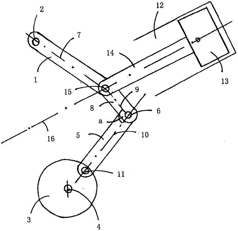
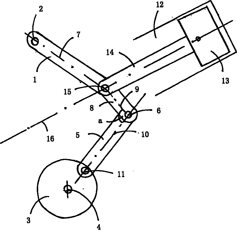
[0026] figure 1 The crank-and-link mechanism depicted in includes a rocker 1 , one end of which is mounted in a fixed manner with its rocker axis 2 on a frame, not shown. The crank linkage mechanism is driven by a crank 3, which is also mounted on the above-mentioned frame in a manner that its axis 4 is fixed. The orientation of the rocker axis 2 and the axis 4 are parallel to each other. The connecting rod 5 is connected via a joint 6 to a section 8 which is bent towards the longitudinal axis 7 of the rocker 1 .

[0027] This curved section 8 is inclined at a fixed angle to the connecting rod 5 compared to the longitudinal axis 7 of the rocker 1 and is preferably produced in one piece with the rocker 1 . Thus, an angle a that varies with the rotational movement of the crank 3 is formed between the longitudinal axis 9 of the section 8 bent towards the connecting rod 5 and the longitudinal axis 10 of the connecting rod 5 . During the rotational movement of the crank 3 , this...


PUM


Abstract

The invention relates to a crank drive, having a frame, which may be formed in particular by a housing, having a rocker (1) positionally fixedly mounted on the frame, having a crank (3) which is positionally fixedly mounted on the frame and which forms the drive output, and having a coupler (5) which connects the rocker (1) and the crank (3), wherein the coupler (5) is articulatedly connected in each case to the crank (3) and to an end, which is situated opposite the positionally fixed mounting (2), of the rocker (1), wherein to drive the crank (3), a first cylinder (12) is provided which has a movably mounted piston (13), wherein the piston (13) and the rocker (1) are articulatedly connected to one another via a push rod (14) such that the axial movement of the piston (13) sets the rocker (1) in an oscillating swinging motion, and wherein the rocker (1) comprises a section (8); which is remote from the positionally fixed mounting of the rocker (1) and which is inclined by a fixed angle towards the coupler (5).

Description

technical field [0001] The present application relates to a crank linkage mechanism. It comprises a frame, which can be formed in particular by a housing, and a rocker mounted on the frame in a stationary manner. Furthermore, the crank mechanism has a crank which is designed as an output shaft and is fixedly mounted on the frame. A connecting rod connects the rocker to the crank. For this purpose, the connecting rods are each articulated to the ends of the crank and rocker opposite the ends intended for stationary mounting. Background technique [0002] Such a crank-link mechanism is used to convert linear reciprocating motion into circular motion. For example, DE1 698 561U shows a double-crank link mechanism with no stop, the transmission mechanism has two rockers, and these two rockers are respectively connected to the crank in the manner of toggle connection through the connecting rod. The rod mechanism is connected. The person operating the double crank linkage appl...

Claims


Application Information

Patent Timeline
Patent Type & Authority Applications(China)
IPC IPC(8): F02B41/04F02B75/32
CPCF02B75/32F02B41/04
Inventor K·赫曼斯
Owner K 赫曼斯
Why Eureka
Try Eureka