Energy production arrangement

A technology of energy and accumulators, which is applied in the field of energy supply devices, can solve problems such as the reduction of total device efficiency, and achieve the effect of efficiency improvement

Inactive Publication Date: 2012-05-23
ROBERT BOSCH GMBH
View PDF3 Cites 106 Cited by
  • Summary
  • Abstract
  • Description
  • Claims
  • Application Information

AI Technical Summary

Problems solved by technology

However, the individual cells are not charged according to the corresponding capacity here, which leads to a reduction in the efficiency of the overall installation

Method used


Image

  • Energy production arrangement
  • Energy production arrangement
  • Energy production arrangement

Examples


Embodiment Construction

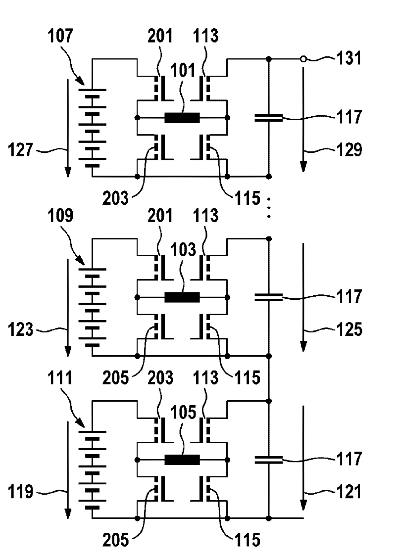
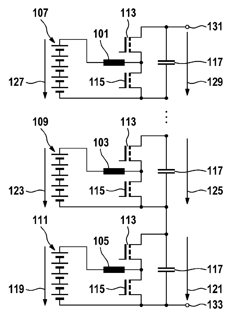
[0021] figure 1 An energy supply arrangement with a certain number of DC choppers 101 , 103 and 105 is shown. The DC chopper 101 is arranged downstream of an energy store 107 , the DC chopper 103 is arranged downstream of an energy store 109 and the DC chopper 105 is arranged downstream of an energy store 111 . Each energy store can consist, for example, of one or more energy store cells. The energy store can be, for example, a motor vehicle battery.

[0022] On the output side, the DC choppers 101 , 103 and 105 are each connected to a switching device comprising two transistors 113 and 115 . On the output side, a smoothing capacitor 117 can be optionally provided respectively.

[0023] exist figure 1 The DC choppers 101 to 105 shown in are preferably connected in series, wherein, for example, the input voltage 119, U mod1 converted to an output voltage of 121, U zkmod1 . Correspondingly, the input voltage 123, U supplied to the DC chopper on the input side via the ener...


PUM


Abstract

The invention relates to an energy production arrangement having a plurality of DC choppers (101, 103, 105) for converting the present input voltages into output voltages, and the plurality of energy stores (107, 109, 111) for providing the input voltages, wherein an energy store is associated with each DC chopper (101, 103, 105), and wherein an output voltage of at least one DC chopper (101, 103, 105) of the plurality of DC choppers (101, 103, 105) can be adjusted as a function of a prescribed target value, in order to individually load the energy store (107, 109, 111) associated with the at least one DC chopper (101, 103, 105).

Description

technical field [0001] The invention relates to the field of providing energy using an energy store, in particular using an electric vehicle battery or a hybrid vehicle battery. Background technique [0002] Known electric vehicle batteries or hybrid vehicle batteries consist of individual battery cells which always have a certain degree of variation in the parameters of homogeneous components, for example with regard to efficiency. In addition, the battery cells are often coupled thermally differently to the environment and thus also heat up differently. In order to achieve a uniform loading of the battery cells, they are usually connected in series so that the same current flows through each battery cell. However, the individual cells are not charged according to the corresponding capacity, which would lead to a reduction in the efficiency of the overall installation. Contents of the invention [0003] The invention is based on the recognition that the efficiency of a ...

Claims


Application Information

Patent Timeline
Patent Type & Authority Applications(China)
IPC IPC(8): H02J7/00B60L50/15
CPCY02T10/7077H02J7/0065Y02T10/7005H02M3/158H02J7/0019H02J2207/20Y02T10/70H02M1/0077H02J7/04
Inventor S.斯潘哈克J.法斯纳克特J.霍伊塞尔
Owner ROBERT BOSCH GMBH
Why Eureka
Try Eureka