
Non-vibrating three-dimensional variable-frequency spraying mechanical hand
A manipulator, three-dimensional technology, applied in the direction of spraying device, etc., can solve the problems of the influence of spraying quality and the instability of the three-dimensional frequency conversion spraying manipulator.
- Summary
- Abstract
- Description
- Claims
- Application Information
AI Technical Summary
Problems solved by technology
Method used
Image

Examples
Embodiment Construction
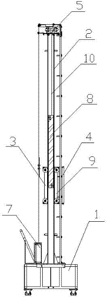
[0009] Such as figure 1 As shown, the three-dimensional frequency conversion spraying manipulator includes a base 1, a hollow column 2, and the column 2 is vertically fixed on the base 1, and a reciprocating assembly 9 is set on the column 2, and the reciprocating assembly 9 includes a sliding fixing frame 3 and a spray gun fixing frame 4 , the sliding fixed frame 4 is sleeved on the column 2, the spray gun fixed frame 4 is fixedly connected to the front end of the sliding fixed frame 3, the upper traction pulley 5 is set at the upper end of the column 2, and the lower traction guide is set at the bottom of the column 2 Wheel 6, between the upper and lower traction pulleys 5,6 winds a traction chain 10, the two ends of the traction chain 10 are respectively fixedly connected to the upper and lower ends of the sliding bracket 3, motor 7 is set on base 1, motor 7 The output end of the drive chain is connected with the lower traction sheave 6, and the counterweight 8 is connected...
PUM
 Abstract
Description
Claims
Application Information