Guide piece device of sliding window

A technology of sliding windows and guides, which is applied to the suspension device of the wing leaf, door/window accessories, wing leaf parts, etc. It can solve problems such as difficult installation and disassembly, easy falling off, and window sash cannot be installed, so as to reduce the cost of mold opening , to ensure the effect of water tightness

Active Publication Date: 2015-03-25
ZYF LOPSKING MATERIAL TECH CO LTD
View PDF10 Cites 0 Cited by
  • Summary
  • Abstract
  • Description
  • Claims
  • Application Information

AI Technical Summary

Problems solved by technology

[0004]1) When the gap between the guide piece and the guide rail of the outer frame is too large, when the sash is opened or closed, it will shake under the external force, and the window will Whistling sound, which seriously affects the watertightness, airtightness and wind pressure resistance of sliding windows;
[0005] 2) When the fit gap between the guide piece and the outer frame guide rail is too small, the guide piece will easily rub against the outer frame guide rail during the push-pull process of the window sash, which will affect the whole window push-pull effect
Or because the matching gap is too small and the rotation angle of the window sash is not enough, the window sash cannot be installed on the outer frame;
[0006]3) In order to ensure a certain gap, the grooves and gaps punched on the upper and lower sides of the window sash and the exposed screw holes also affect the aesthetics of the whole window to varying degrees;
[0007]4) Considering the installation of the window s

Method used


Image

  • Guide piece device of sliding window
  • Guide piece device of sliding window
  • Guide piece device of sliding window

Examples


Embodiment Construction

[0043] The advantages of the present invention will be further described below in conjunction with the accompanying drawings and specific embodiments.

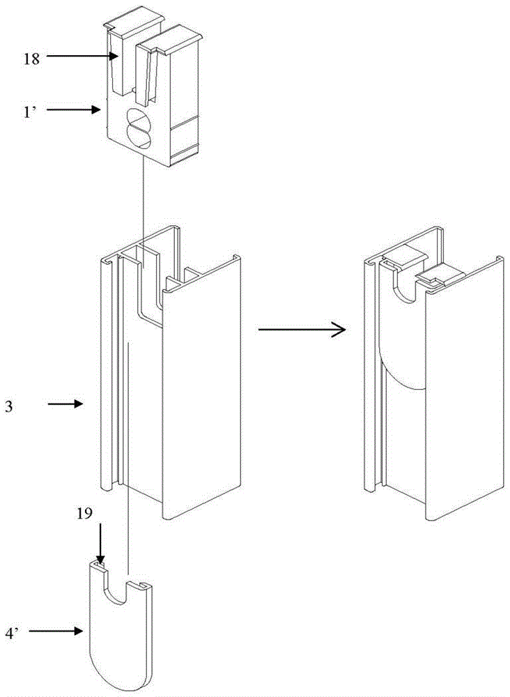
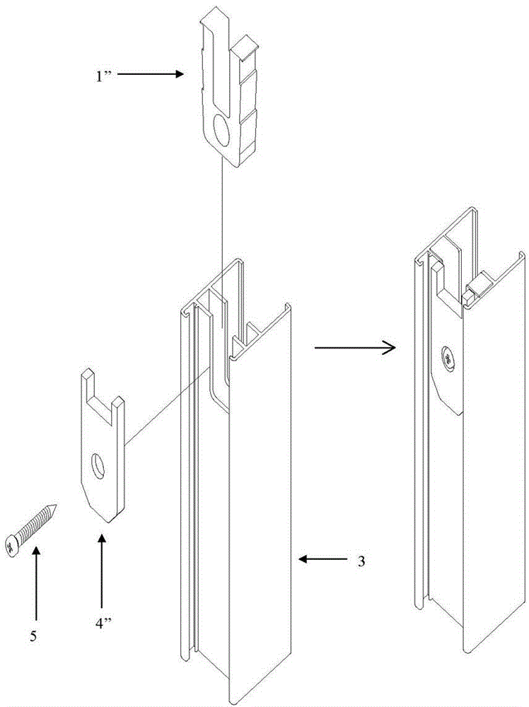
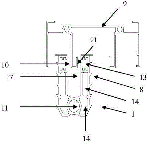
[0044] See image 3 and Figure 4 , is a schematic structural diagram of an embodiment of the present invention. This embodiment is described by taking the guide device as an example. A guide device for a sliding window includes a guide body 1 and an adjusting device 4, the guide body has two symmetrical legs 8 and a circular hole 11, and the two legs 8 form a groove 7, preferably a U-shaped groove, the guide The two legs 8 of the sheet main body 1 are provided with guides along the direction of the sliding window outer frame guide rail 91, preferably designed as guide grooves 13, and the guide grooves 13 are symmetrically arranged on the top of the two legs 8, and the guide sheet main body 1 and the outer frame The guide body fit gap 10 between the guide rails 91 of the horizontal material 9 and the depth of the guide body...


PUM


Abstract

The invention relates to a guide piece device of a sliding window, which comprises a main guide piece body inserted into an end part of a window sash vertical material, wherein the main guide piece is provided with two supporting legs, and a groove is formed between the two supporting legs; and each supporting leg of the main guide piece body is provided with a guide device in the direction a guide rail of an outer frame of the sliding window. The guide piece device also comprises an adjusting device with a concave rabbet which can be inserted into the groove of the main guide piece body, and a guide piece which is matched with the guide device in a male and female inserting way is correspondingly arranged; and the guide rail of the outer frame of the sliding window passes through the concave rabbet, and the adjusting device also comprises a clamping device matched with the main guide piece body. The invention has the advantages that: in the design of the guide piece, the problem that what size a matching clearance is reserved is avoided, the flexible sliding of the window is better realized, and the water tightness, air tightness, wind resistance and attractiveness are ensured.

Description

Technical field [0001] The present invention involves a guidance device, which specifically says a guide device that involves a sliding window. Background technique [0002] A kind of accessory is mainly installed on the upper and lower end of the sneer -to -fan window. The connection between the push window and the fan of the sliding window fan and the sneer fan is mainly tightened through the screw. ThereforeConnect to the screw holes on the sneaker horizontal material.Because the inner frame of the aluminum alloy sliding window is designed for hollow, the guide sheet can block the hollow parts at both ends of the vertical material, thereby improving the air density of the entire window.The empty part of the frame guide, stable push fans. [0003] The implementation principle of the sliding window function is to rolling friction through the roller rails installed with the roller and frame of the outer frame through the horizontal material, thereby achieving the opening and turn...

Claims


Application Information

Patent Timeline
IPC IPC(8): E05D13/00
Inventor 吴明福
Owner ZYF LOPSKING MATERIAL TECH CO LTD
Why Eureka
Try Eureka