Acryl backplate type illuminating reflector

An acrylic and back-plate-type technology, which is applied in the direction of reflectors, lighting devices, lighting and heating equipment, etc., can solve the problems of affecting imaging quality, image comparison misjudgment, etc., and achieve the effect of improving imaging quality

Inactive Publication Date: 2012-05-30
KUSN MINGJIU ELECTROMECHANICAL
View PDF0 Cites 0 Cited by
  • Summary
  • Abstract
  • Description
  • Claims
  • Application Information

AI Technical Summary

Problems solved by technology

[0004] Although the existing technology can obtain multiple angle images of the object 1 to be measured at the same time, since the light source 3 and the reflector 31 are not at the same angle, shadows will be formed

Method used


Image

  • Acryl backplate type illuminating reflector
  • Acryl backplate type illuminating reflector
  • Acryl backplate type illuminating reflector

Examples


Embodiment Construction

[0014] The following description of the embodiments refers to the accompanying drawings to illustrate specific embodiments in which the invention may be practiced. The directional terms mentioned in the present invention, such as "up", "down", "front", "back", "left", "right", "top", "bottom", etc., are only for reference to the attached drawings. direction. Therefore, the directional terms used are used to illustrate and understand the present invention, but not to limit the present invention.

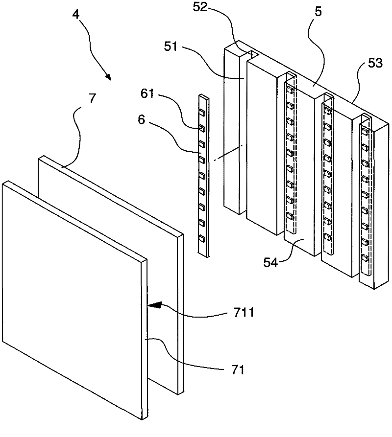
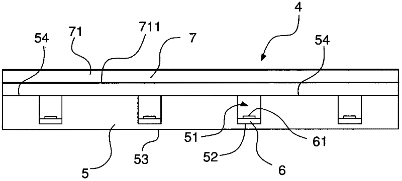
[0015] Please refer to Figure 2 to Figure 4 The acrylic back plate illuminating reflector of the present invention shown, wherein figure 2 It is a three-dimensional exploded view of the acrylic backboard illuminating reflector of the present invention; image 3 It is a combined side view of the acrylic back plate illuminating reflector of the present invention; Figure 4 It is a combined partial cross-sectional view of an acrylic back plate illuminating reflector of the present ...


PUM


Abstract

The invention discloses an acryl backplate type illuminating reflector, which comprises a metal backplate, a plurality of circuit boards, a diffusion plate and a semi-transparent lens, wherein the acryl backplate is a plate capable of diffusing light, a plurality of holding grooves are formed on one surface of the acryl plate, a base is arranged at the bottom of each holding groove, and a reflection surface is formed on the back face of the acryl backplate; the circuit boards are arranged in the bases in the holding grooves, and a plurality of light emitting modules are arranged on the surfaces of the circuit boards; the diffusion plate is a plate which is transparent, but cannot be perspective completely, and the back face of the diffusion plate is attached to the acryl backplate; and the back face of the semi-transparent mirror is provided with a semi-reflection coating, and the semi-reflective coating is attached to the front surface of the diffusion layer. The semi-transparent mirror type self-lighting reflector disclosed by the invention is capable of providing a uniform lighting source and reflecting an image at the same time.

Description

【Technical field】 [0001] The present invention relates to a self-illuminating reflector, in particular to an acrylic backplate illuminating reflector which utilizes an acrylic backplate to reflect a light source so that the front of the reflector can reflect images and simultaneously provide light from the back. 【Background technique】 [0002] With the miniaturization of products, the size of various parts is gradually reduced, and the inspection procedures and inspection equipment in the production process are also adjusted to the miniature size. Nowadays, the analytical ability of digital images has been greatly improved, and digital images taken with optical lenses combined with computer automatic inspection equipment are gradually becoming popular. Many inspection tasks that were performed manually in the past have also been replaced by automatic optical inspection equipment. [0003] Please refer to figure 1 As shown, it is a schematic configuration diagram of automati...

Claims


Application Information

Patent Timeline
IPC IPC(8): F21V5/04F21V7/22F21V29/00F21Y101/02F21V29/503F21V29/508
Inventor 张旻郁
Owner KUSN MINGJIU ELECTROMECHANICAL
Why Eureka
Try Eureka