Light guide element and light source device

A light-guiding element and light-emitting light source technology, which is applied in the direction of optical elements, electric light sources, lighting devices, etc., can solve the problems affecting the light output effect of linear light sources, etc.

Inactive Publication Date: 2012-05-30
UNITED WIN CHINA TECH +1
View PDF5 Cites 0 Cited by
  • Summary
  • Abstract
  • Description
  • Claims
  • Application Information

AI Technical Summary

Problems solved by technology

At this time, the structural design of the light guide cylinder may affect the light output effect of the linear light source

Method used


Image

  • Light guide element and light source device
  • Light guide element and light source device
  • Light guide element and light source device

Examples


Embodiment Construction

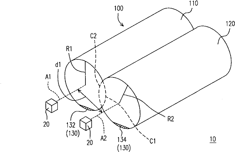
[0029] figure 1 It is a schematic diagram of a light source device composed of a light guide element according to a first embodiment of the present invention. Please refer to figure 1 , the light source device 10 includes a light guide element 100 and a plurality of light emitting sources 20 . The light guide element 100 at least includes a first columnar portion 110 and a second columnar portion 120, the first columnar portion 110 is a part of a first reference cylinder C1, and the second columnar portion 120 is a part of a second reference cylinder C2, The first cylindrical part 110 and the second cylindrical part 120 are integrally formed, wherein a distance d1 between the axis A1 of the first reference cylinder C1 and the axis A2 of the second reference cylinder C2 is smaller than the radius of curvature of the first reference cylinder C1 The sum of R1 and the radius of curvature R2 of the second reference cylinder C2 is combined to form a union. In addition, the light ...


PUM


Abstract

The invention provides a light guide element and a light source device. The light guide element comprises at least one first columnar part and at least one second columnar part, wherein the first columnar part is a part of a first reference cylinder; the second columnar part is a part of a second reference cylinder; and the first columnar part and the second columnar part are integrally molded, wherein the distance between the axes of the first reference cylinder and the second reference cylinder is less than the aggregation of the radiuses of curvatures of the first reference cylinder and the second reference cylinder.

Description

technical field [0001] The invention relates to an optical element and a light source device with the optical element, in particular to a light guide element and a light source device with the light guide element. Background technique [0002] Since the liquid crystal display panel does not have the characteristic of self-illumination, a backlight module must be placed under the liquid crystal display panel to provide the light source required by the liquid crystal display panel. Traditional backlight modules generally use cold cathode fluorescent lamps (CCFL) as the light source of the backlight module. [0003] However, with the advancement of semiconductor technology, light-emitting diodes (light-emitting diodes, LEDs) can achieve more and more power, and the intensity of light emitted is getting higher and higher. It has many advantages such as power saving, long service life, environmental protection, fast start-up, small size, etc., which makes the application level o...

Claims


Application Information

Patent Timeline
Patent Type & Authority Applications(China)
IPC IPC(8): G02B6/00F21V8/00F21S8/00
Inventor 叶志庭陈冰彦黄国瑞
Owner UNITED WIN CHINA TECH
Why Eureka
Try Eureka