
Laser irradiation apparatus and laser processing system using the same

A laser irradiation and laser processing technology, which is applied in metal processing, laser welding equipment, metal processing equipment, etc., can solve the problems of reducing laser utilization efficiency and not being able to use a universal micro-mirror array, and achieve good light utilization efficiency Effect

Inactive Publication Date: 2009-01-28
OLYMPUS CORP
View PDF8 Cites 7 Cited by
  • Summary
  • Abstract
  • Description
  • Claims
  • Application Information

AI Technical Summary

Problems solved by technology

[0004] However, as described in Patent Document 2 (Japanese Unexamined Patent Application Publication No. 2006-350123), such a laser processing device has the following problem: when the incident angle of the laser light relative to the micromirror array is fixed, When the wavelength is changed in the state, the phenomenon that the utilization efficiency of the laser light is reduced
[0011] In the technique described in Patent Document 2, since the inclination angle of the micromirror is adjusted, a general-purpose micromirror array cannot be used due to light of multiple wavelengths, and there is a problem that an expensive micromirror array needs to be used.

Method used


Image

  • Laser irradiation apparatus and laser processing system using the same
  • Laser irradiation apparatus and laser processing system using the same
  • Laser irradiation apparatus and laser processing system using the same

Examples


no. 1 Embodiment approach

[0028] A laser irradiation device according to a first embodiment of the present invention and a laser processing system using the same will be described.

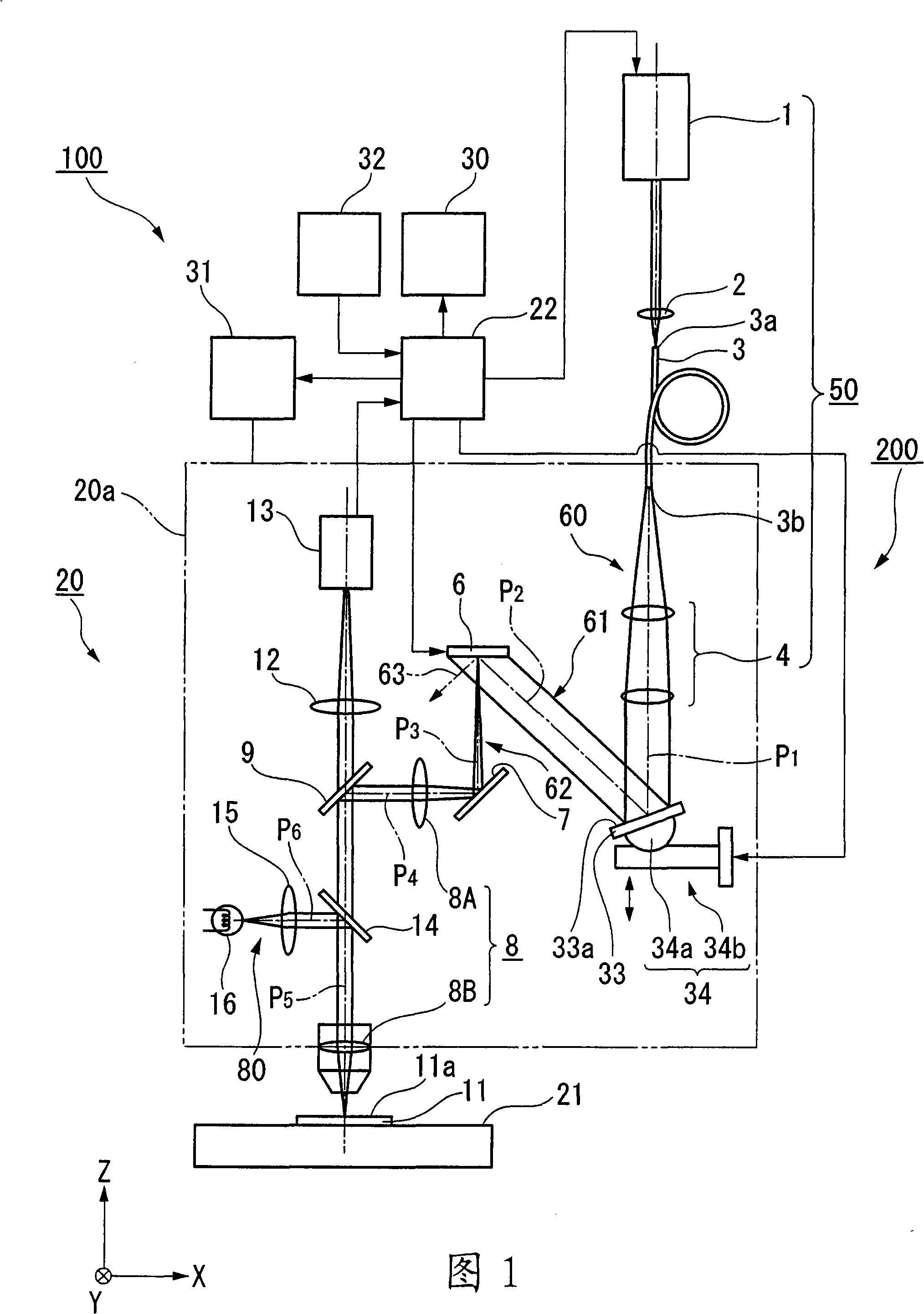
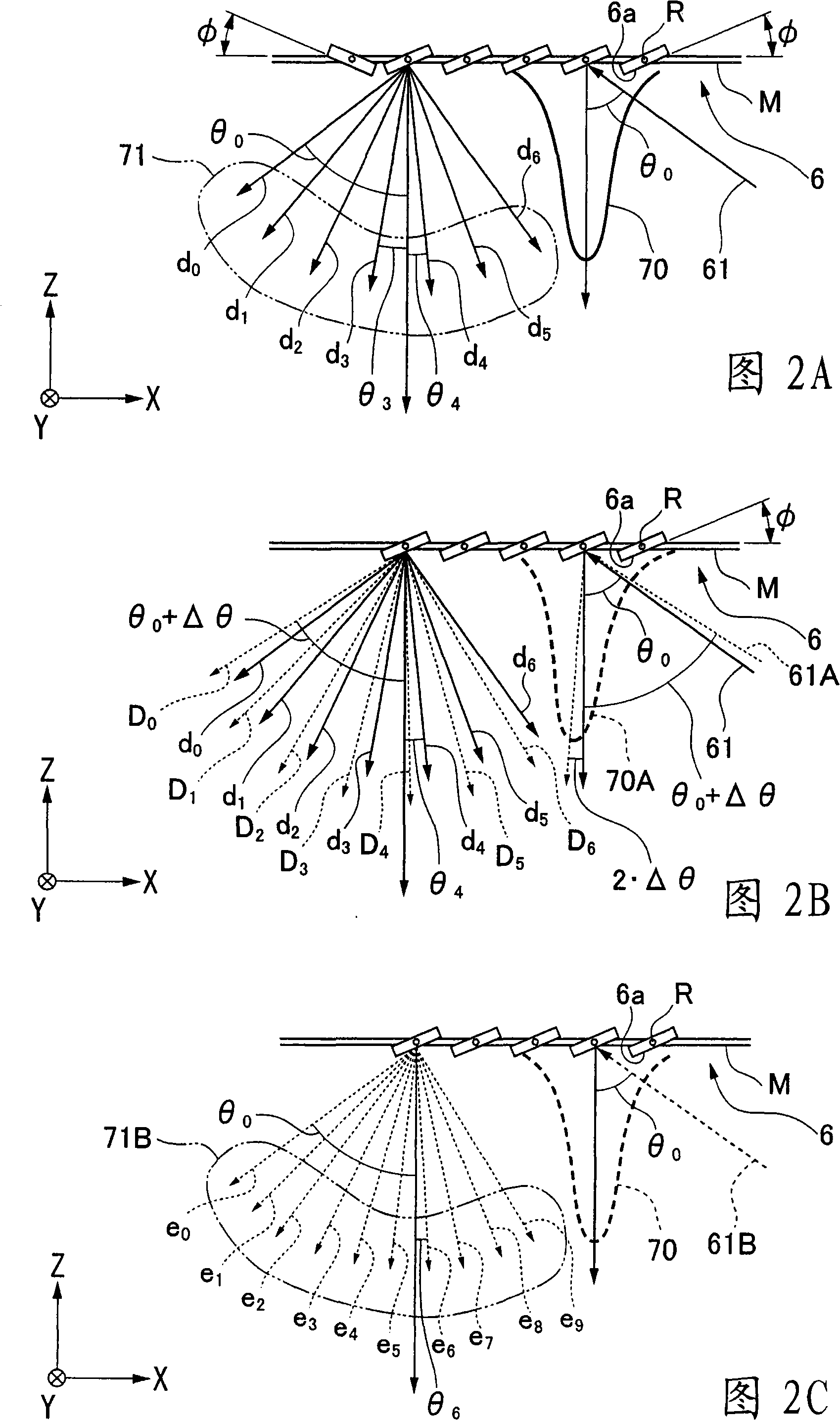
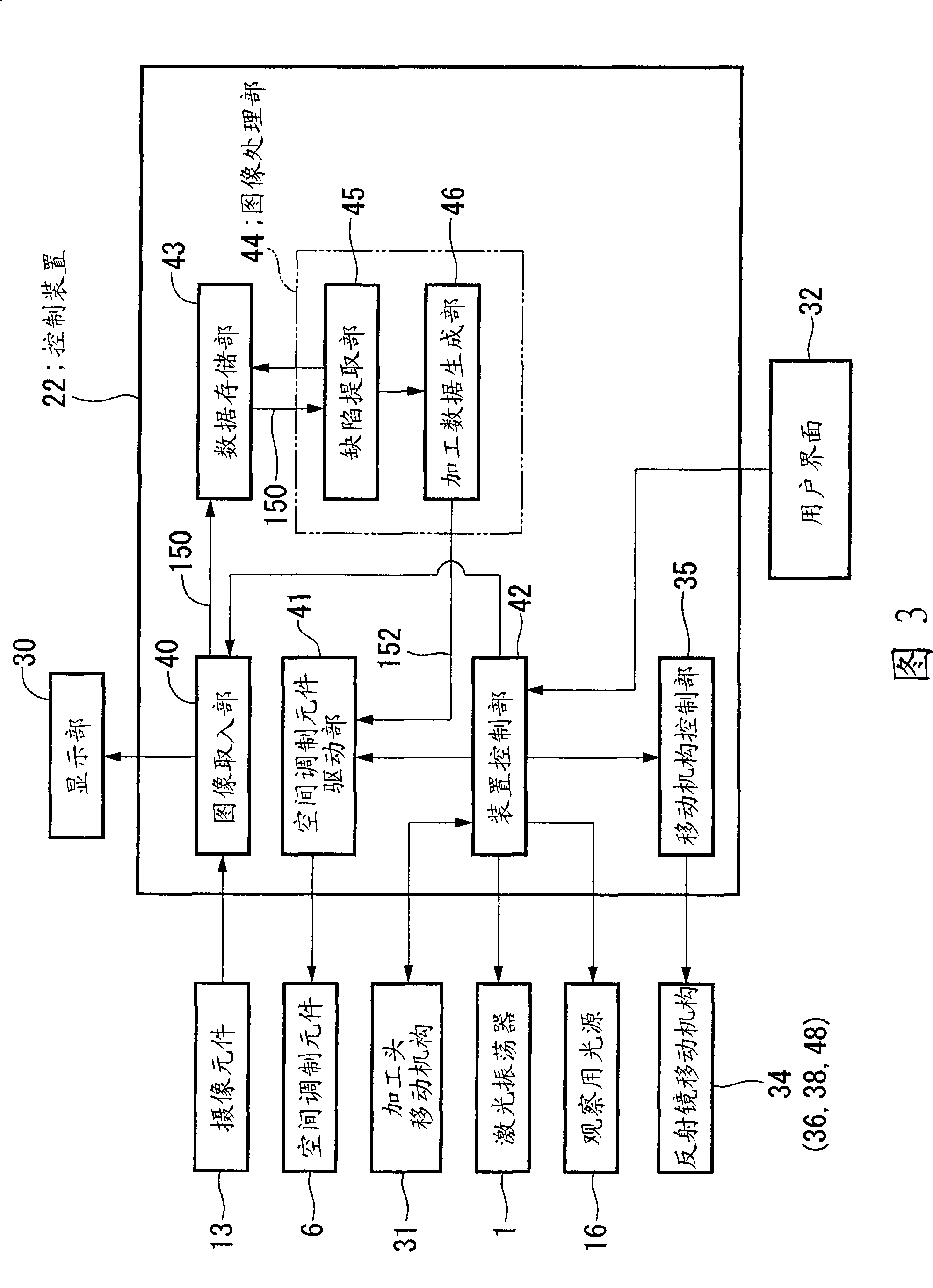
[0029] 1 is a schematic cross-sectional view including an optical axis, showing a schematic configuration of a laser irradiation device and a laser processing system using the same according to an embodiment of the present invention. 2A, 2B, and 2C are schematic cross-sectional views illustrating a diffraction phenomenon of a spatial modulation element of a laser irradiation device according to an embodiment of the present invention. 3 is a functional block diagram showing a schematic configuration of a control device of a laser processing system according to an embodiment of the present invention.

[0030] In order to facilitate the reference direction, the XYZ coordinate system in the figure is set to the same positional relationship in each drawing, the vertical direction is represented as the Z axis, the horizontal pla...


PUM


Abstract

The invention relates to a laser irradiating device and a laser processing system using the same. The laser processing system comprises a laser source; a reflecting mirror for causing the laser emitted from the laser source to deflect by a deflection surface supported movably; a reflector moving mechanism for configuring the deflection surface to deflect correspondingly to an optical axis P1 of the laser and move in the optical axis P1 direction; a space modulating element for modulating the laser deflected by the reflector in space and forming opening light towards the irradiated surface; and a projection optical system for projecting the opening light formed by the space modulating element to the processed surface.

Description

technical field [0001] The present invention relates to a laser irradiation device and a laser processing system using the laser irradiation device. Background technique [0002] Conventionally, a laser processing device (laser irradiation device) is known that performs processing by irradiating a laser beam to a desired region of a workpiece. For example, in the manufacture of liquid crystal displays and the like, laser trimming devices are known as devices for trimming defective parts such as wiring patterns on glass substrates and unnecessary residues present on photomasks used for exposure. [0003] For example, the laser processing device described in Patent Document 1 (Japanese Unexamined Patent Publication No. 8-174242) has: a laser source; a processing table on which a workpiece is placed; ), by turning ON / OFF (ON / OFF) control to switch the angles of a plurality of reflective mirrors of the micro-mirror array to form arbitrary pattern shapes on the workpiece. [00...

Claims


Application Information

Patent Timeline
IPC IPC(8): G02B26/08B23K26/00B23K26/04B23K26/03B23K26/042
CPCB23K26/032B23K26/04B23K26/0643B23K26/083B23K26/0869B23K2101/36
Inventor 有贺润子中村达哉高桥浩一
Owner OLYMPUS CORP
Learn More