Optical picking-up head and optical device

A technology of optical pickup and optical axis, applied in optical recording head, integrated optical head device, optics, etc., can solve the problems of lack of practicability and poor light utilization efficiency

Inactive Publication Date: 2003-09-03
VICTOR CO OF JAPAN LTD
View PDF0 Cites 0 Cited by
  • Summary
  • Abstract
  • Description
  • Claims
  • Application Information

AI Technical Summary

Problems solved by technology

[0006] However, in the former prior art example, since the paths from the laser light sources 51, 57 to the half mirror 53 are different for each wavelength, the first laser light source 51 and the first photosensitive element substrate 50 and the second laser light source 51 are arranged to be different from each other. The position of light source 57 and photosensitive element substrate 56 is in the position that separates respectively, just can not make optical pick-up head miniaturization like this
[0007] On the other hand, in the latter prior art example, although the first laser light source 60 and the second laser light source 61 are arranged close to each other and have the same path for each wavelength, due to the path of the incident light to the disk 64 and the light reflected from the disk 64 The paths of the reflected light are different, so the positions of the first and second laser light sources 60, 61 and the photosensitive element substrate 65 are arranged separately, so that the optical pick-up head cannot be miniaturized like the former
[0008] Here, although it is conceivable to make the light of each wavelength on the same path, and make the path of the incident light on the disk coincide with the path of the reflected light reflected from the disk, it is necessary to have light of different wavelengths on the common optical axis. A device for diffracting and spectroscopically separately
It's just that if such a device is configured, the light utilization efficiency from the laser light source to the photosensitive element through the disc becomes very poor, so it lacks practicality.
[0009] On the other hand, for the optical pickup head of the previous prior art example, when manufacturing the optical device, such as Figure 8 As shown, the optical device 70 that fixes the first laser light source 51, the first photosensitive element substrate 50 and the first holographic device 52 in the box and the second laser light source 57, the second photosensitive element substrate 56 and the second The holographic device 58 is fixed in the casing and the optical device 71 can be miniaturized respectively, but they cannot be assembled to make a small single optical device.
[0010] For the optical pickup head of the latter prior art example, when manufacturing the optical device, such as Figure 9 As shown, the optical device 73 that fixes the first laser light source 60 and the first photosensitive element substrate 61 in the box can be miniaturized, but except for the first and second laser light sources 60, 61, the photosensitive The element substrate 65, etc. are also concentrated together to make a small single optical device

Method used


Image

  • Optical picking-up head and optical device
  • Optical picking-up head and optical device
  • Optical picking-up head and optical device

Examples


Embodiment Construction

[0073] Embodiments of the present invention will be described below with reference to the drawings.

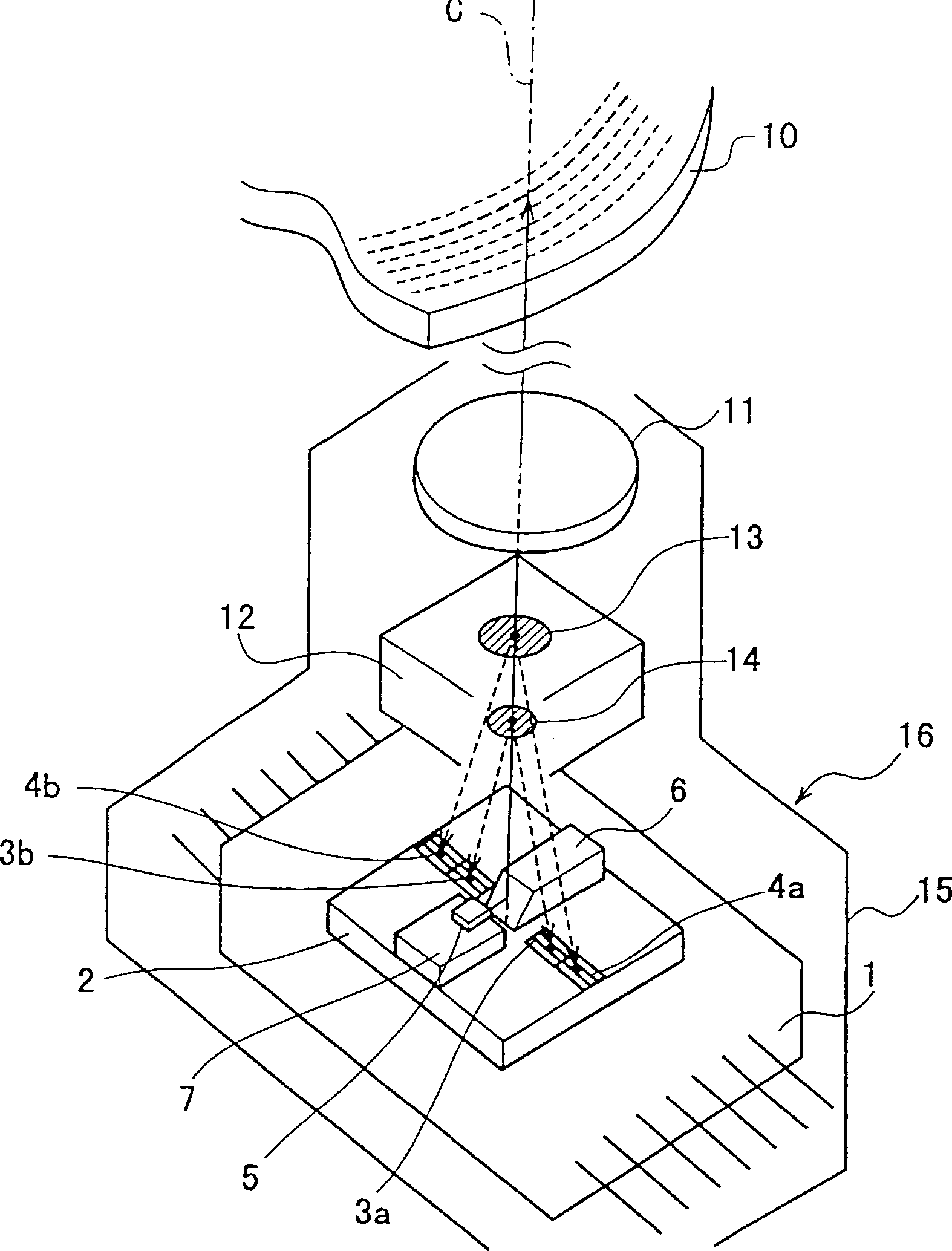
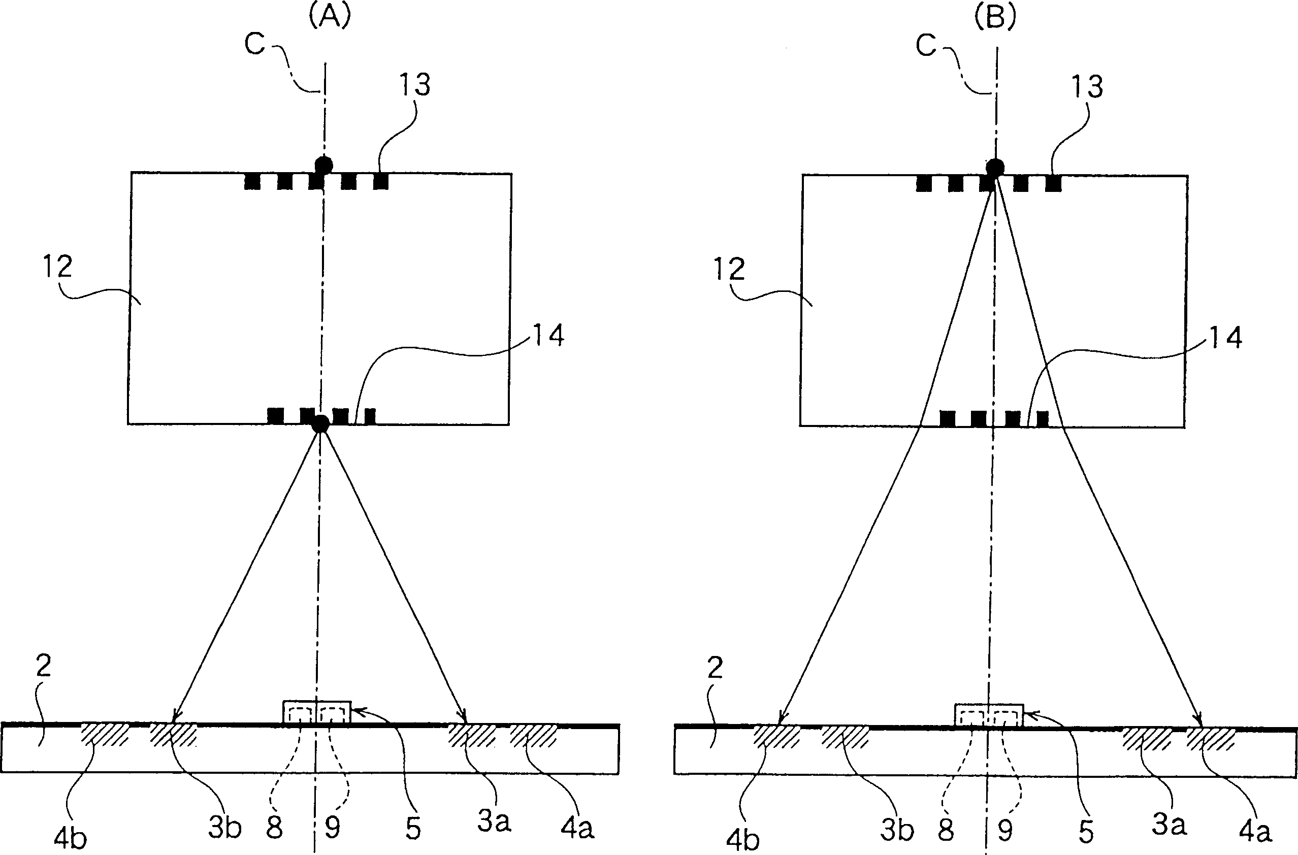
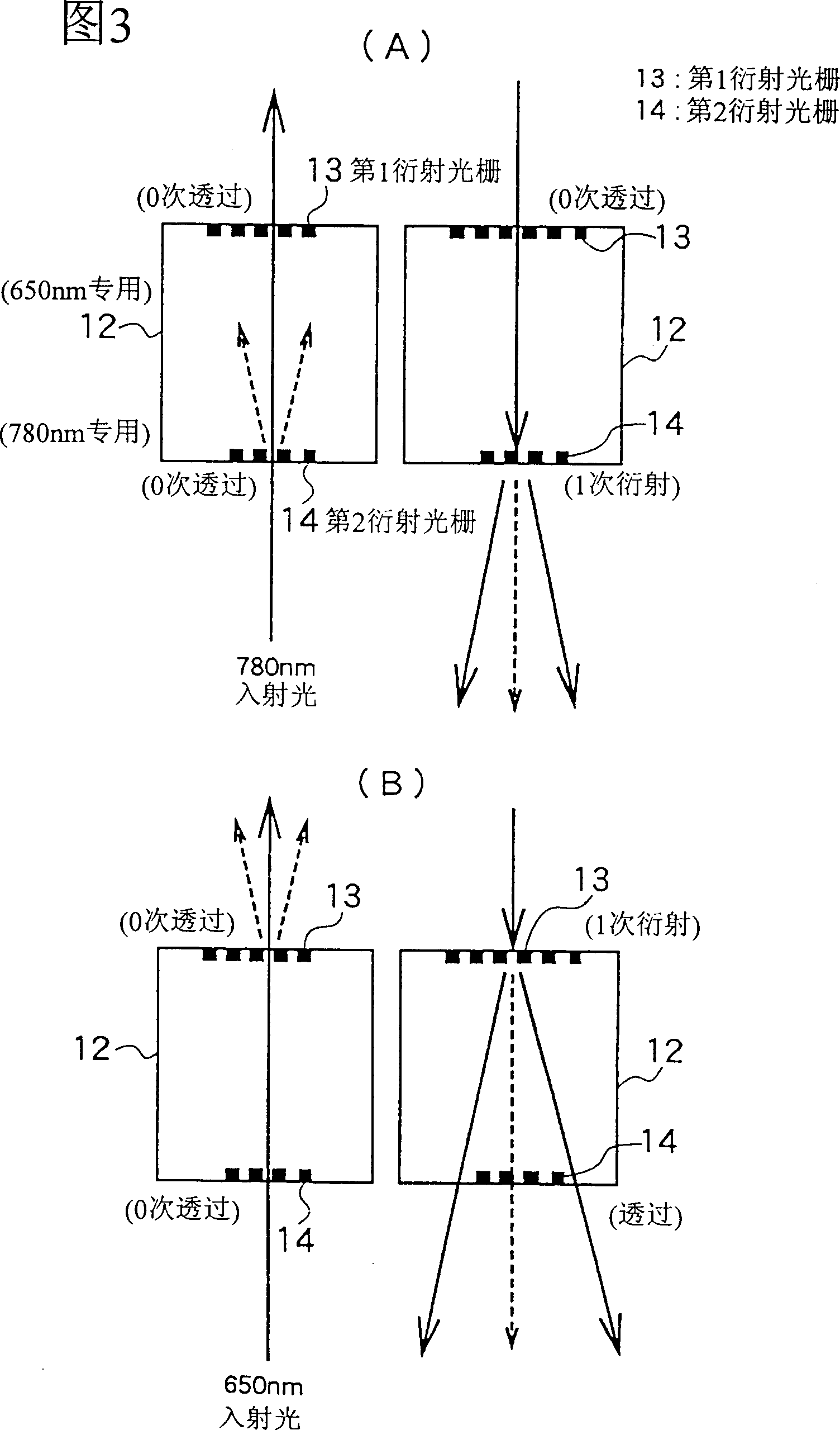
[0074] figure 1 one Figure 5 Shows the first embodiment of the present invention. figure 1 It is a simplified oblique view of the optical pickup head; figure 2 (A) represents the irradiation position of the emitted light of the first laser light source on the photosensitive element substrate; figure 2 (B) shows the irradiation position of the light emitted by the second laser light source on the photosensitive element substrate; FIG. 3(A) shows a state diagram in which the light emitted by the first laser light source is diffracted and transmitted by the first and second diffraction gratings ; Fig. 3 (B) shows that the output light of the second laser light source is diffracted and transmitted by the first and second diffraction gratings.

[0075] exist figure 1 - In FIG. 3, the photosensitive element substrate 2 is fixed on the wiring substrate 1, and four photosen...


PUM


Abstract

An optical pickup of this invention includes a first laser beam source having a wave length of 780 nm and a second laser beam source having a second wave length of 650 nm wherein the first laser beam source and the second laser beam source are disposed in the vicinity of each other, emission lights from the first laser beam source and the second laser beam source are emitted along substantially the same optical axis and a reflected light from the information recording medium is returned along the optical axis; the first diffraction grating, the second diffraction grating and the light receiving device substrate are disposed in order, the first diffraction grating is substantially transparent for a wave length of 780 nm and diffracts a wave length of 650 nm, and the second diffraction grating is substantially transparent for a wave length of 650 nm while it diffracts a wave length of 780 nm.

Description

technical field [0001] The present invention relates to the optical pick-up head and the optical device that the reproduction device of the information recording medium such as optical disc etc. adopts, relate in particular to be suitable for DVD (Digital Versatile Disc, digital versatile disk) and CD-R (Compact Disc-Writeonce, only write-once disc) interchangeable playback system device. Background technique [0002] As for the CD (Compact Disc, optical disc) of the generally popular consumer disc system, a higher-density DVD system solution has been proposed and commercialized, and is beginning to be popularized. In the DVD player of this playback device, in order to avoid the repetition of the device and the complexity of use, in addition to the necessary CD interchangeable playback, CD-Rs that can be played back on the CD player are also required to have It is a subject to develop technology for reproducing discs of various specifications such as interchangeable reprodu...

Claims


Application Information

Patent Timeline
IPC IPC(8): G11B7/09G02B5/18G02B5/32G11B7/00G11B7/12G11B7/123G11B7/125G11B7/1275G11B7/135G11B7/1353
CPCG11B7/1353G11B7/1205G11B2007/0006G11B7/1275G11B7/123
Inventor 大山实
Owner VICTOR CO OF JAPAN LTD
Why Eureka
Try Eureka