Luminous flux control member and light emitting apparatus

A technology for light beam control components and light-emitting elements, which is applied to optical elements, lighting devices, components of lighting devices, etc., can solve the problem of ineffective use of leaked light, etc., and achieve the effect of excellent light utilization efficiency

Active Publication Date: 2014-10-01
ENPLAS CORP
View PDF5 Cites 6 Cited by
  • Summary
  • Abstract
  • Description
  • Claims
  • Application Information

AI Technical Summary

Problems solved by technology

However, the Fresnel lens 40 described in Patent Document 1 has a problem that the leaked light leaked from the reflective Fresnel lens portion 42 cannot be effectively used.

Method used


Image

  • Luminous flux control member and light emitting apparatus
  • Luminous flux control member and light emitting apparatus
  • Luminous flux control member and light emitting apparatus

Examples


Embodiment Construction

[0067] Hereinafter, embodiments of the present invention will be described in detail with reference to the drawings.

[0068] [Structure of light beam control member and light emitting device]

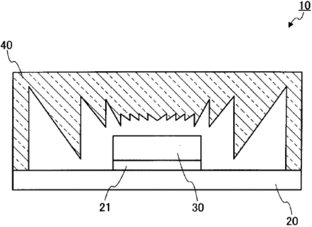
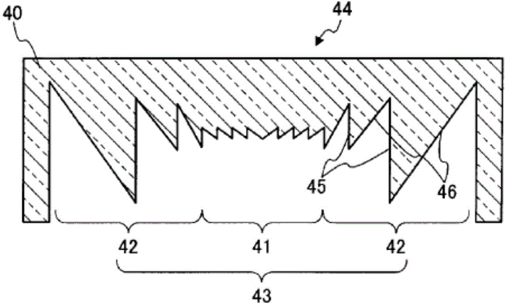
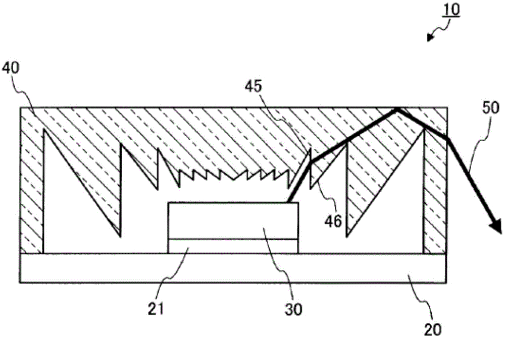
[0069] 3 and 4 are diagrams showing the configuration of the light flux control member 100 according to one embodiment of the present invention. Figure 3A is a top view of the light beam control member 100, Figure 3B 3C is a side view of the light flux control member 100 , and 3C is a bottom view of the light flux control member 100 . Figure 4A yes Figure 3A with Figure 3C A cross-sectional view of line A-A is shown, Figure 4B yes Figure 4A A partial enlarged cross-sectional view of the area enclosed by the dashed line in . Figure 5 It is a cross-sectional view showing the structure of a light emitting device 200 according to an embodiment of the present invention.

[0070] Such as Figure 5 As shown, the light flux control member 100 of this embodiment is used in combi...


PUM


Abstract

A luminous flux control member (100) provided by the invention has a light input region (110), to which light having been outputted from a light emitting element (210) is inputted; and a light output region (150), from which the light having been inputted from the light input region (110) is outputted. The input region (110) has a refracting section (120), a reflection fresnel lens section (130) which is positioned outside of the refracting section (120), and a reflecting surface (140) which is positioned outside of the reflection fresnel lens section (130). The reflecting surface (140) reflects the light which has been inputted to the reflection fresnel lens section (130), and which has not been reflected (the light leaked from the reflection fresnel lens section (130)), toward the light output region (150).

Description

technical field [0001] The present invention relates to a light flux control member for controlling light distribution of light emitted from a light emitting element, and a light emitting device including the light flux control member. Background technique [0002] In recent years, light-emitting devices (LED flashes) using light-emitting diodes (hereinafter also referred to as "LEDs") as light sources have been used as light-emitting devices for video cameras from the viewpoint of energy saving and miniaturization. As such a light emitting device, a light emitting device combining an LED and a Fresnel lens is known (for example, refer to Patent Document 1). [0003] Figure 1A It is a sectional view of the light-emitting device described in Patent Document 1. FIG. Such as Figure 1A As shown, the light-emitting device 10 described in Patent Document 1 includes a substrate 20 , a substrate 21 for a light source, a light source 30 including a light-emitting element and a pho...

Claims


Application Information

Patent Timeline
IPC IPC(8): G02B17/08F21V5/04G02B3/08G02B17/00H01L33/58
CPCF21Y2101/02G02B3/08F21V13/04F21V5/04G02B19/0061G02B19/0028F21V5/045H01L33/58F21Y2115/10
Inventor 齐藤共启
Owner ENPLAS CORP
Why Eureka
Try Eureka