Eureka AIR delivers breakthrough ideas for toughest innovation challenges, trusted by R&D personnel around the world.

System and method for testing universal interface

A test system and general interface technology, applied in error detection/correction, instrumentation, electrical digital data processing, etc., can solve the problems of low serial port data throughput, unable to meet the needs of testing, and the test platform is not fully automated. Achieve the effect of improving test efficiency and reducing test labor costs

Inactive Publication Date: 2012-05-30
SHANGHAI HUAHONG INTEGRATED CIRCUIT
View PDF3 Cites 23 Cited by
  • Summary
  • Abstract
  • Description
  • Claims
  • Application Information

AI Technical Summary

Problems solved by technology

The disadvantage of the first architecture is that the total code volume is limited by the code capacity of the test chip, and random and automated testing cannot be completed
This problem can be solved in the second architecture, but in the second architecture, manual interface switching is required, the data throughput of the serial port is too low, the card reader equipment corresponding to a single interface is used, and automatic transmission of multiple interfaces at the same time cannot be realized. question
These problems will seriously affect the productivity and test coverage of software testing
The need to manually switch interfaces indicates that the test platform is not truly fully automated
The data throughput of the serial port is too low, which will be a potential bottleneck for the application of large data transmission
The use of card reader equipment corresponding to a single interface is not conducive to the unification of software test scripts, and at the same time increases equipment costs, and cannot automatically transmit multiple interfaces at the same time
In today's situation of rapid development of multi-interface chip applications, it cannot meet the needs of testing

Method used


Image

  • System and method for testing universal interface
  • System and method for testing universal interface

Examples


Embodiment Construction

[0026] specific implementation plan

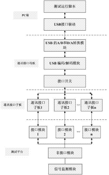
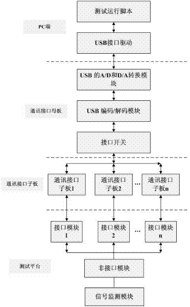
[0027] The following is attached figure 1 The general interface test system and its test method proposed by the present invention are described in detail.

[0028] The PC end is connected with the communication interface motherboard through the USB interface, and the script command is sent to the communication interface motherboard through the USB driver program at the PC end. The communication interface motherboard performs A / D conversion, protocol analysis, interface switching and other processing on the signal. The communication interface template is connected to the communication interface sub-board through a hard line, and the communication interface sub-board performs conversion according to each port protocol. The communication interface sub-board is connected to the test platform for test communication, and the test platform interfaces receive and test respectively.

[0029] The communication interface motherboard is mainly comp...


PUM


Abstract

The invention provides a method of a system for testing a universal interface. The system consists of a personal computer (PC) end test script, a communication interface mother board, a communication interface sub-board and a test platform, wherein the test platform is a field programmable gate array (FPGA) or application specific integrated circuit (ASIC) platform; a PC end is connected with the communication interface mother board through a universal serial bus (USB) interface; the communication interface mother board is connected with the communication interface sub-board through a hard wire; the communication interface sub-board is connected with the test platform for test communication; and a communication sub-interface can be made independently according to a test requirement. The invention also provides a method for implementing the system for testing the universal interface. By utilizing the system and the method, the requirement for simultaneously testing by multi-interface test application can be met; the USB interface meets the requirement for high data throughput; and by utilizing the automatic test method, the test labor cost is reduced effectively and the test efficiency is improved.

Description

technical field [0001] The invention relates to an integrated circuit test system and a test method, in particular to a general interface test system and a test method. Background technique [0002] With the continuous development of integrated circuit technology and the continuous deepening of the application field of integrated circuits (hereinafter referred to as "IC"), the design complexity and performance complexity of IC chips have been substantially improved compared with before, which is of great importance to chip design companies and chip application manufacturers. The system test plan puts forward higher requirements. [0003] Currently, IC chip design companies generally adopt two kinds of system testing schemes: first, establish a server-based software chip simulation platform. This solution is mainly aimed at testing the coverage rate of hardware codes and limited module functions; secondly, by building a board-level FPGA (Field Programmable Gate Array) or ASI...

Claims


Application Information

Patent Timeline
IPC IPC(8): G06F11/267
Inventor 丁颖
Owner SHANGHAI HUAHONG INTEGRATED CIRCUIT
Why Eureka
Eureka Blog
Learn More