Drawer type card connector

A card connector and drawer type technology, which is applied in the field of switch terminal structure, can solve the problems of increasing assembly difficulty, increasing manufacturing process and assembly difficulty, and achieving the effects of simple structure, reduced manufacturing process and reduced assembly difficulty.

Active Publication Date: 2012-05-30
FUYU ELECTRONICS TECH (HUAIAN) CO LTD +1
View PDF6 Cites 37 Cited by
  • Summary
  • Abstract
  • Description
  • Claims
  • Application Information

AI Technical Summary

Problems solved by technology

[0004] However, the card connector with this structure is provided with two switch terminals, which are respectively installed on the insulating body. There are many parts and assembly is difficult, which increases the manufacturing process and increases the difficulty of assembly.

Method used


Image

  • Drawer type card connector
  • Drawer type card connector
  • Drawer type card connector

Examples


Embodiment Construction

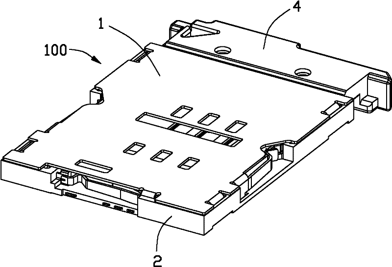
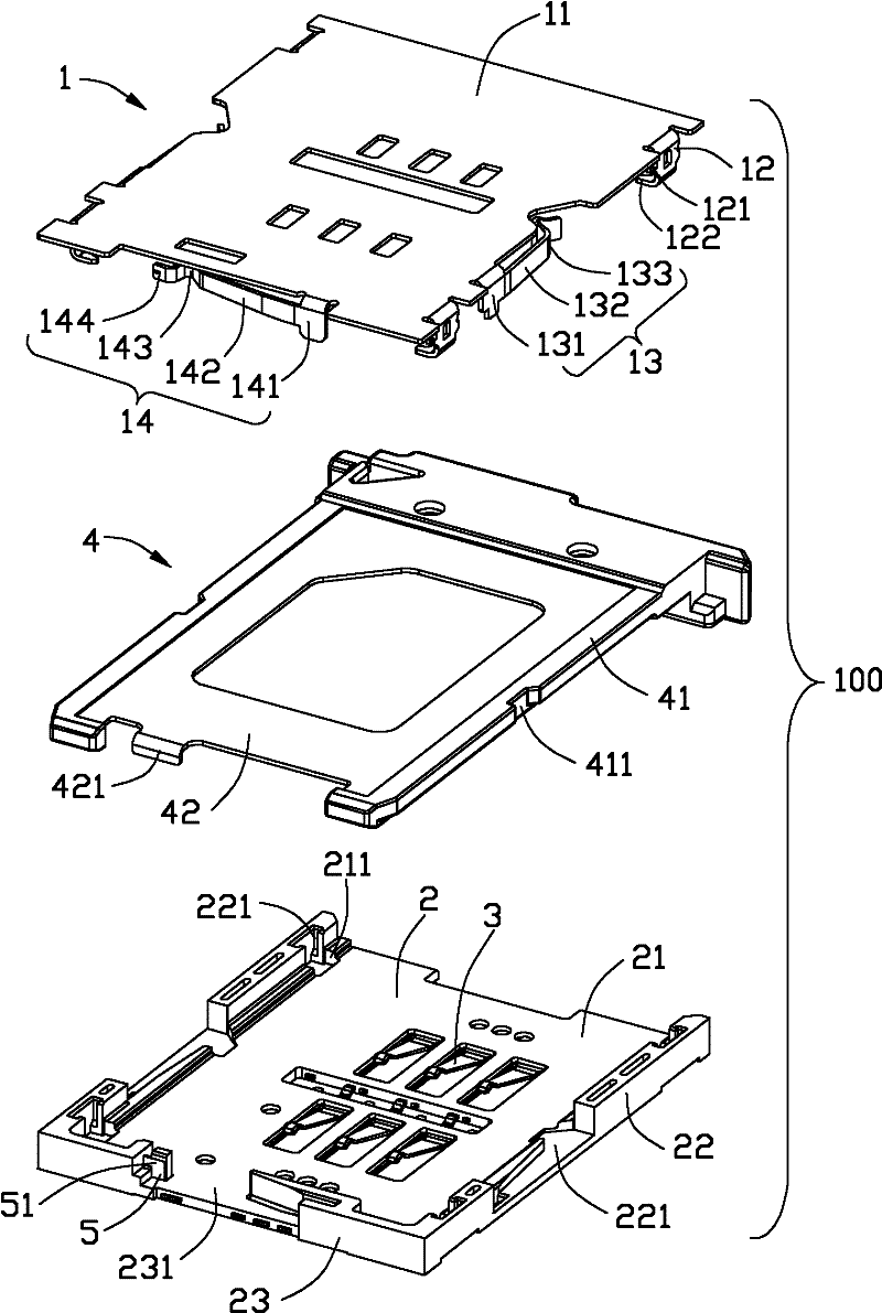
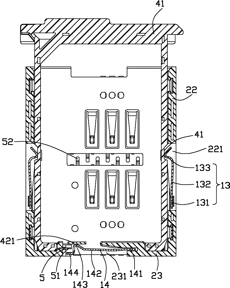
[0012] see Figure 1 to Figure 3 As shown, the drawer type card connector 100 of the present invention includes an insulating body 2, a plurality of conductive terminals 3 accommodated in the insulating body 2, a shielding shell 1 made of metal covering the insulating body 2, and a shielding housing 1 accommodated in the insulating body 2. The sliding seat 4 and the switch terminal 5 used to carry the electronic card (not shown) in the aforementioned receiving space. The shielding case 1 and the insulating body 2 jointly form a receiving space.

[0013] In this embodiment, the conductive terminal 3 is integrally formed and held on the insulating body 2 , and the portion of the conductive terminal 3 in contact with the electronic card (not shown) protrudes into the aforesaid accommodating space.

[0014] The insulating body 2 includes a bottom wall 21 , side walls 22 disposed on both sides of the bottom wall 21 , and a front wall 23 disposed at a front end. The conductive ter...


PUM


Abstract

The invention discloses a drawer type card connector, which comprises an insulating body, a plurality of conducting terminals, a shielding shell and a sliding seat, wherein the conducting terminals are accommodated in the insulating body; the shielding shell is covered on the insulating body; the sliding seat is used for bearing an electronic card; the shielding shell and the insulating body form an accommodating space; the sliding seat slides in the accommodating space; a switch terminal is accommodated in the insulating body; the front end of the shielding shell is provided with a wafer; the wafer can be electrically connected with a switch terminal; the sliding seat slides from a switch-on position to a switch-off position to drive the switch terminal and the wafer to be switched on or off; the switch terminal comprises a wafer which is integrated with the shielding shell; and a clamping sheet is integrated arranged with the shielding shell. The drawer type card connector has the advantages of simple structure, convenience for molding, reduction in manufacturing procedures and reduction in assembling difficulty.

Description

【Technical field】 [0001] The invention discloses a drawer type card connector, in particular to a switch terminal structure of the drawer type card connector. 【Background technique】 [0002] The existing drawer-type card connector usually has an insulating body for accommodating several conductive terminals, and a shielding shell covering the insulating body. The two cooperate to form a storage space for storing electronic cards. Sliding seat for electronic cards. In the card connector, a switch terminal is usually provided to detect whether the electronic card is inserted into a preset position. [0003] As disclosed in Taiwan New Patent Announcement No. M359106, the switch terminals include two, which are respectively arranged on the front end of the insulating body, and are respectively welded to the printed circuit board. When the electronic card is inserted, the switch terminals are pressed to separate or combine the two. , so as to realize the detection function of t...

Claims


Application Information

Patent Timeline
Patent Type & Authority Applications(China)
IPC IPC(8): H01R12/52H01R12/71H01R13/02H01R13/46H01R13/629H01R13/71
Inventor 谭世杰周建波
Owner FUYU ELECTRONICS TECH (HUAIAN) CO LTD
Why Eureka
Try Eureka