Supercharge Your Innovation With Domain-Expert AI Agents!

Stable on-resistance switch circuit

A technology of switches and sensitive resistors, which is applied in the field of signal transmission switching systems and can solve problems such as performance differences

Active Publication Date: 2012-05-30
FAIRCHILD SEMICON SUZHOU +1
View PDF5 Cites 6 Cited by
  • Summary
  • Abstract
  • Description
  • Claims
  • Application Information

AI Technical Summary

Problems solved by technology

For some applications and signaling protocols, this range of on-resistance may result in unacceptable performance variations for specific switches or switches with process variations

Method used


Image

  • Stable on-resistance switch circuit
  • Stable on-resistance switch circuit
  • Stable on-resistance switch circuit

Examples


example 15

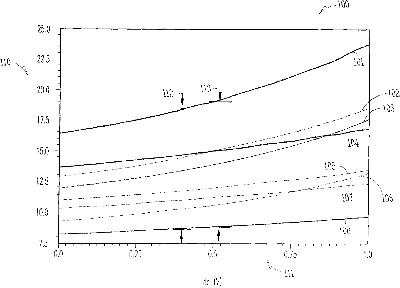
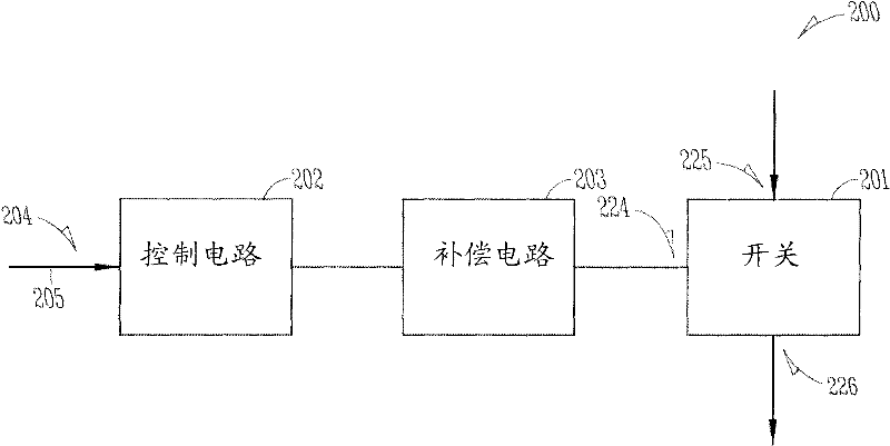
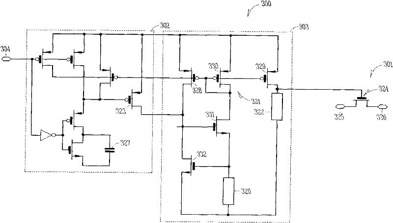
[0066] In Example 15, a method comprising: receiving a control voltage at a control node of a switch, adjusting the control voltage over an ambient temperature range to maintain the first and second nodes of the switch when the switch is in the on state between the specified resistance. The adjustment of the control voltage includes generating a sense voltage by adjusting the threshold voltage of the transistor, providing the sense voltage on a temperature-insensitive resistor to generate a sense current, using the sense current and a current mirror to provide a mirror current, and using the mirror current and a thermally sensitive A resistor provides the control voltage.

[0067] In Example 16, the providing the sense current of any one or more of Examples 1-15 optionally includes utilizing a polysilicon resistor.

[0068] In Example 17, the utilizing polysilicon resistors of any one or more of Examples 1-16 optionally includes utilizing P+ polysilicon resistors.

[0069] I...


PUM


Abstract

This document discusses, among other things, a compensation circuit configured to modulate a control voltage of a switch over a range of ambient temperatures during a conduction state of the switch to maintain a specified resistance between first and second nodes of the switch. The compensation circuit can include a temperature-insensitive resistor configured to provide a sense current, a current mirror configured to provide a mirror current using the sense current, and a temperature-sensitive resistor configured to provide the control voltage using the mirror current.

Description

technical field [0001] The present invention relates, among other things, to signal transmission switch systems and in particular, but not limited to, signal transmission switches having stable on-resistance. Background technique [0002] Electronic circuits and systems often include electronic switches. Electronic switches can be used to pass an analog signal to a circuit path, or to prevent an analog signal from being passed to a circuit path. This type of switch is sometimes called an analog switch or a pass switch to distinguish this type of switch from a digital switch that changes an output state in response to an input but does not pass the received signal through. The switch is designed to respond to a nominal control voltage that turns the switch into an "on" state. This control voltage determines the expected on-resistance. However, even if the control voltage is maintained at the nominal value, the physical characteristics and environmental conditions of the sw...

Claims


Application Information

Patent Timeline
Patent Type & Authority Applications(China)
IPC IPC(8): H03K17/14
CPCH03K17/145
Inventor N·加涅J·L·斯图兹S·马卡卢索
Owner FAIRCHILD SEMICON SUZHOU
Features
  • R&D
  • Intellectual Property
  • Life Sciences
  • Materials
  • Tech Scout
  • Unparalleled Data Quality
  • Higher Quality Content
  • 60% Fewer Hallucinations
Learn More