Safety ensuring method of implantable medical system and system thereof

An implantable medical and implantable technology, applied in the direction of user identity/authorization verification, etc., can solve the problem of being unable to control implanted medical devices, and achieve the effect of preventing threats

Active Publication Date: 2012-05-30
SCENERAY
View PDF4 Cites 37 Cited by
  • Summary
  • Abstract
  • Description
  • Claims
  • Application Information

AI Technical Summary

Problems solved by technology

[0006] In addition, if the patient accidentally loses or damages the patient controller, a new patient controller needs to be replaced, so that only the replaced new patient controller can control the implantable medical device while the original patient controller is abolished, so that even if others pick up Obtaining or repairing the original patient controller will no longer control the implantable medical device

Method used


Image

  • Safety ensuring method of implantable medical system and system thereof
  • Safety ensuring method of implantable medical system and system thereof
  • Safety ensuring method of implantable medical system and system thereof

Examples


Embodiment approach 1

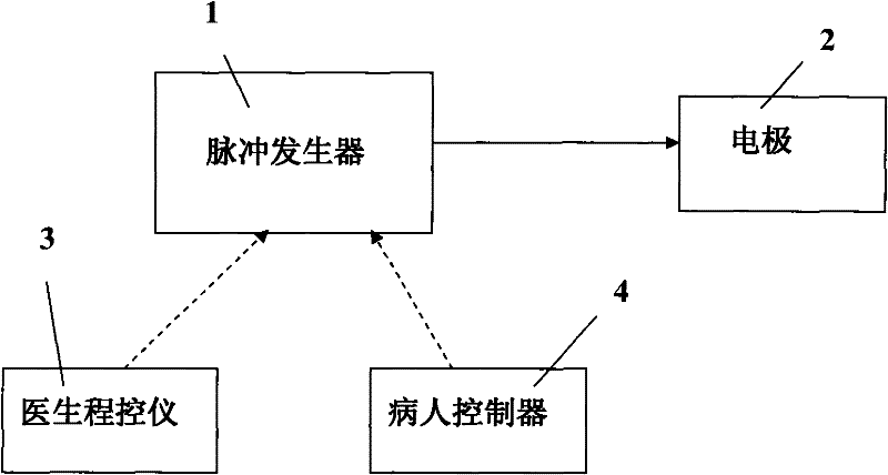
[0040] refer to figure 1 , taking the implantable electrical nerve stimulation system as an example, it mainly includes a pulse generator 1 and electrodes 2 implanted in the body, as well as a doctor program controller 3 and a patient controller 4 located outside the body. The pulse generator 1 is electrically connected to the electrode 2, so that the pulse generated by the pulse generator 1 is transmitted to the electrode 2, so as to electrically stimulate the nerve target to achieve a therapeutic effect. When the doctor programmer 3 and the patient controller 4 can adjust the output parameters such as the amplitude, frequency, and pulse width of the pulse generator 1, the doctor programmer 3 also has specific functions such as querying patient information, which is more functional than the patient controller 4. powerful.

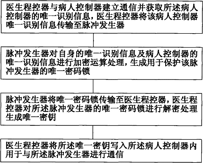
[0041] refer to figure 2 , the safety binding method between the patient controller and the pulse generator of the present invention comprises the follow...

Embodiment approach 2

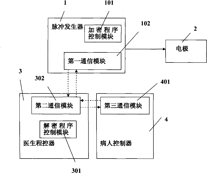
[0054] refer to Figure 4 , a one-to-one secure binding method between the patient controller and the pulse generator, comprising the following steps:

[0055] A: The doctor programmer 3 establishes communication with the patient controller 4 and obtains the unique identification information of the patient controller 4, and the doctor programmer 3 establishes communication with the pulse generator 1 and obtains the unique identification information of the pulse generator 1;

[0056] B: The doctor program controller 3 encrypts the unique identification information of the pulse generator 1 and the unique identification information of the patient controller 4 to generate a unique combination lock for protecting the pulse generator;

[0057] C: The doctor program controller 3 decrypts the unique password lock to generate a unique key;

[0058] D: The doctor programmer 3 writes the unique password lock into the pulse generator 1 and writes the unique key into the patient controll...


PUM


Abstract

The invention discloses a safety ensuring method of an implantable medical system and a system thereof. The method is characterized by: carrying out encryption function processing to only identification information of an implantable medical device and the only identification information of a corresponding patient controller; writing a generated only cipher lock into the implantable medical device; writing an only secret key into the patient controller after decryption processing is performed to the only cipher lock and the only secret key is generated. Therefore, only can the patient controller possessing the only secret key be communicated with the implantable medical device. When a patient damages or losses the original patient controller, the new patient controller can be configured by using the method of the invention. Even if others get the damaged or lost original patient controller, because the secret key in the original patient controller can not match with the new cipher lock of the implantable medical device, a threat to the health of the patient, which is generated by misusing or maliciously using the patient controller of the other patient, can be prevented.

Description

technical field [0001] The invention relates to an implanted medical system, in particular to a one-to-one safe binding method for a patient controller and an implanted medical device and the implanted medical system. Background technique [0002] Implantable medical systems usually include implantable nerve electrical stimulation systems, implantable cardiac electrical stimulation systems (commonly known as cardiac pacemakers), and implantable drug infusion systems. Among them, implantable electrical nerve stimulation systems include deep brain electrical stimulation DBS, implantable cerebral cortex electrical stimulation CNS, implantable spinal cord electrical stimulation SCS, implantable sacral nerve electrical stimulation SNS, implantable vagus nerve electrical stimulation VNS, etc. [0003] Taking the implanted electrical nerve stimulation system as an example, it mainly includes a pulse generator implanted in the body, electrodes and external control devices. Among th...

Claims


Application Information

Patent Timeline
Patent Type & Authority Applications(China)
IPC IPC(8): H04L9/32
Inventor 邹德刚孟杰
Owner SCENERAY
Why Eureka
Try Eureka