Method and system for protecting layer 2 tunneling protocol (L2TP) network

A network and network equipment technology, applied in the protection method and system field of L2TP network, can solve problems such as not supporting L2TP user backup, unable to guarantee normal progress of L2TP session, etc., to achieve the effect of improving service reliability and user experience

Active Publication Date: 2012-05-30
ZTE CORP
View PDF4 Cites 18 Cited by
  • Summary
  • Abstract
  • Description
  • Claims
  • Application Information

AI Technical Summary

Problems solved by technology

[0006] In view of this, the main purpose of the present invention is to provide an L2TP network protection method and system to solve the problems that the e

Method used


Image

  • Method and system for protecting layer 2 tunneling protocol (L2TP) network
  • Method and system for protecting layer 2 tunneling protocol (L2TP) network
  • Method and system for protecting layer 2 tunneling protocol (L2TP) network

Examples


Embodiment 1

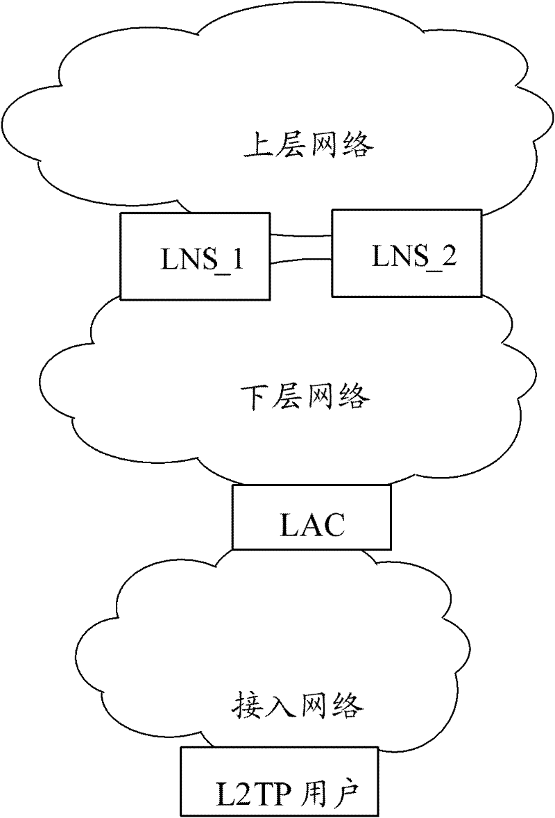
[0060] In this embodiment, the L2TP network topology is as follows image 3 As shown, it includes LNS_1, LNS_2, and LAC devices, wherein the link state detection is performed between LNS_1 and LNS_2 through the BFD protocol, and the LNS device state switching is performed through VRRP.

[0061] In this embodiment, to realize the process of troubleshooting in the L2TP network, refer to Figure 4 As shown, it specifically includes the following steps:

[0062] Step 401, performing active and standby configurations on LNS_1 and LNS_2 respectively;

[0063] Specifically, run the VRRP protocol between LNS_1 and LNS_2, configure their respective VRRP addresses on LNS_1 and LNS_2, and configure priority information on LNS_1 and LNS_2 respectively, where the priority of LNS_1 is greater than that of LNS_2, In this way, LNS_1 is configured as the active state, LNS_3 is in the standby state, and LNS_3 is designated as the backup device of LNS_1. LNS_1 receives the online request of th...

Embodiment 2

[0083] In this embodiment, the L2TP network topology is as follows Figure 5As shown, it includes three LNS devices, LNS_1, LNS_2, and LNS_3, and two LAC devices, LAC_1 and LAC_2. Among them, LAC_1 corresponds to LNS_1, LAC_2 corresponds to LNS_2, LNS_1 and LNS_2 are active devices, LNS_3 is a backup device, and the connection between LNS_1 and LNS_3 Run the BFD protocol between LNS_2 and LNS_3 to detect the link status, and run VRRP to switch between the active and standby states, realizing the function of using one LNS to back up L2TP users for multiple LNSs.

[0084] In this embodiment, to realize the process of troubleshooting in the L2TP network, refer to Figure 6 As shown, it specifically includes the following steps:

[0085] Step 601, performing active and standby configurations on LNS_1, LNS_2, and LNS_3 respectively;

[0086] Specifically, run the VRRP protocol between LNS_1 and LNS_3, and between LNS_2 and LNS_3, configure LNS_1 and LNS_2 as active LNSs, and LNS_...


PUM


Abstract

The invention discloses a method for protecting a layer 2 tunneling protocol (L2TP) network. The method comprises the following steps that: a reserved L2TP network server (LNS) backs up information of the current online L2TP user on a master LNS, information of an L2TP tunnel corresponding to the L2TP user and information of an L2TP session; when the master LNS or a chain on which the master LNS is placed fails, the reserved LNS and the master LNS are subjected to master and reserved state switching; and the reserved LNS updates a route according to the backed information of the L2TP tunnel and the backed information of the L2TP session, and forwards user flow. The invention also discloses a system for protecting the L2TP network. By the system and the method, the failure of the LNS equipment and the chain on which the LNS equipment is placed cannot influence normal service of the L2TP user, and the L2TP user and an L2TP access concentrator (LAC) cannot notice the generation and the recovery of the failure, so that the failure in the L2TP network is eliminated, and the user experience of the L2TP network is improved effectively.

Description

technical field [0001] The present invention relates to virtual private network (VPN, Virtual Private Network) technology, in particular to a method and system for protecting an L2TP network. Background technique [0002] In VPN, the main process of the existing troubleshooting technology is as follows: firstly perform user backup, so that the access point (AN, Access Node) adopts dual uplinks to access dual service nodes SN (SN, Service Node), wherein one One SN is the primary device, and the other SN is the backup device. The access ports of the primary SN correspond to the backup ports of the backup SN. The primary and backup SNs use Virtual Router Redundancy Protocol (VRRP, Virtual Router Redundancy Protocol) and Bidirectional Forwarding Detection (BFD, Bidirectional Forwarding Detection) technology to switch states. The active SN synchronizes the accessed user information to the standby SN. When the standby SN receives the user information transmitted by the active SN,...

Claims


Application Information

Patent Timeline
IPC IPC(8): H04L12/56H04L12/24H04L12/46
CPCH04L41/0663H04L12/4633H04L45/00
Inventor 范亮袁博冷通
Owner ZTE CORP
Why Eureka
Try Eureka