Membrane valve

A diaphragm valve and diaphragm technology, applied in the direction of control valves, valve devices, functional valve types, etc., to achieve the effect of perfect sealing effect

Active Publication Date: 2012-05-30
UNITHER THERAPEUTIK
View PDF6 Cites 10 Cited by
  • Summary
  • Abstract
  • Description
  • Claims
  • Application Information

AI Technical Summary

Problems solved by technology

[0007] However, it has the important disadvantage that the ring rests only on i

Method used


Image

  • Membrane valve
  • Membrane valve
  • Membrane valve

Examples


Embodiment Construction

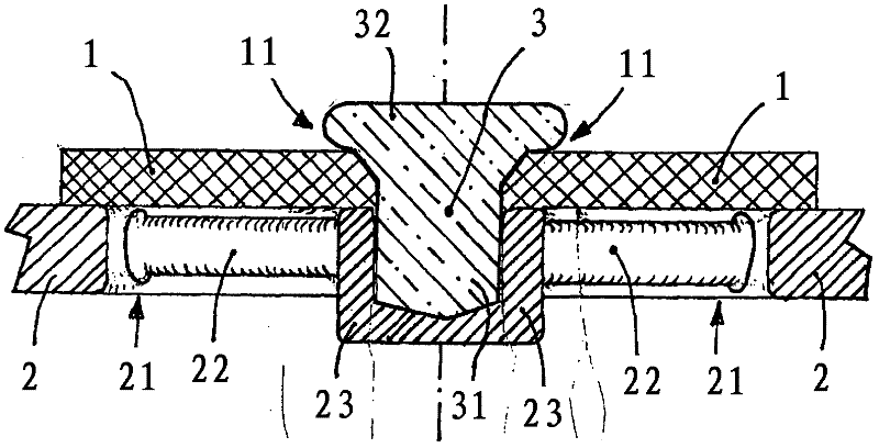
[0031] figure 1 A cross-sectional view of a diaphragm valve according to the invention is drawn in . The rotational symmetry of the illustrated embodiment is indicated by the dash-dot line in the center. Two sections of the frame 2 can be seen on the outermost side. The frame 2 surrounds the air inlet 21, which is in the figure 1 Two are visible in , as they are interrupted in the center by bracket 23 . The carrier 23 is connected to the frame 2 , which surrounds the air inlet opening 21 in a circular manner, via the webs 22 , similarly to a spoked wheel.

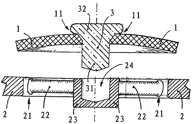
[0032] figure 1 The section of the membrane 1 is shown in cross-hatching. The membrane 1 rests with its outer edge on the frame 2 . figure 2 shows how the membrane can rise in this region from the frame 2 by the outflowing breathing air and thus open a path for the gas to flow through.

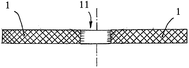
[0033] exist figure 1 The fastening hole 11 is indicated by an arrow in the center of the membrane 1 . In the embodiment shown h...


PUM


Abstract

The invention relates to a membrane valve, in particular for inhalation devices, comprising a planar membrane (1) made of permanently flexible material, a frame (2), which has an air opening that is somewhat smaller than the membrane, at least one web (22), which connects the frame to a retainer (23) that is arranged approximately at the center of the air opening, and a pin (3), the shaft of which extends through a fastening opening approximately at the center of the membrane and is located in a retaining opening in the retainer, wherein the membrane lies on the frame in the rest state and wherein the pin is spread to form a head, the distance of which to the membrane is small in comparison to the thickness of the membrane or which head lies on the membrane, and the diameter of the shaft near the head (32) is greater than the diameter of the fastening opening,; and the diameter of the shaft at the free end of the shaft (31) is approximately equal to the diameter of the fastening opening.

Description

technical field [0001] The present invention relates to a diaphragm valve, in particular for an inhaler, comprising: a planar diaphragm of permanently flexible material; a frame having an air inlet slightly smaller than the diaphragm; at least one slat, the At least one slat connects the frame to a bracket disposed approximately in the center of the air inlet; and a pin whose stem extends approximately in the center of the diaphragm through a retaining hole and in a retaining hole of the bracket wherein the diaphragm is at rest placed on the frame in the state. Background technique [0002] Valves are needed in a variety of systems for directing breathing air for humans and other living things. The usual aim is to enable the living organism to breathe out without hindrance, for which purpose the diaphragm is lifted from the frame by the pressure of the breath expelled from the living being, on which the diaphragm rests in the resting state. The breathing air can then be ex...

Claims


Application Information

Patent Timeline
IPC IPC(8): F16K15/14
CPCF16K15/148Y10T137/7892Y10T137/789A61M11/02A61M16/06F16K15/16F16K17/18
Inventor 约阿希姆·克恩
Owner UNITHER THERAPEUTIK
Why Eureka
Try Eureka