Casting machine and casting machine valve

A technology of pouring machine and valve, applied in the direction of transportation and packaging, cocoa, confectionery, etc., to achieve the effect of large flow and good closing effect

Inactive Publication Date: 2011-04-13
BUEHLER AG
View PDF14 Cites 4 Cited by
  • Summary
  • Abstract
  • Description
  • Claims
  • Application Information

AI Technical Summary

Problems solved by technology

This leads to: This pressure difference first rises rapidly

Method used


Image

  • Casting machine and casting machine valve
  • Casting machine and casting machine valve
  • Casting machine and casting machine valve

Examples


Embodiment Construction

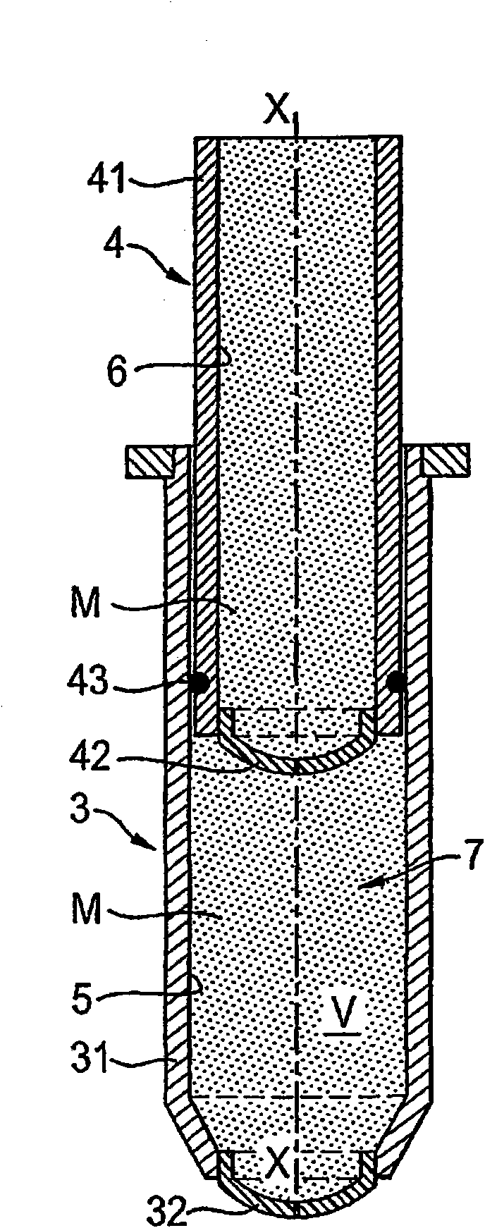
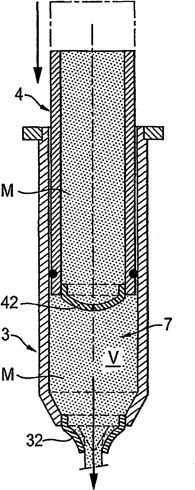
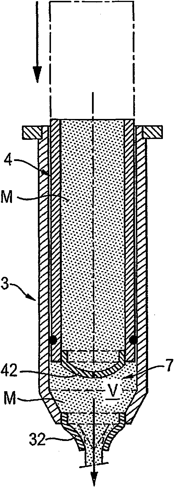
[0061] according to figure 1 A configuration of a dosing unit 3 , 4 is shown, which has a lower valve block 3 and an upper valve block 4 . The dosing unit 3, 4 is an essential component of the pressure generating device according to the invention.

[0062] The lower valve block 3 contains a plurality of lower valve passages 5 arranged side by side and parallel to each other, the cross-section of which is preferably circular. Each lower valve channel 5 is delimited by a channel wall 31 which is preferably cylindrical. At the lower end of a lower valve passage 5 there is a lower valve 32 and at the upper end of the lower valve passage 5 there is an upper valve 42 . Via the channel wall 31 , the lower valve 32 and the upper valve 42 define a dosing chamber whose volume V is variable and is formed by the variable section of the lower valve channel 5 .

[0063] The upper valve block 4 also includes a plurality of upper valve passages 6 arranged side by side and parallel to each...


PUM


Abstract

The invention relates to a casting machine (1) for casting a flowable mass (M), in particular a flowable mass with suspended solid particles. Said casting machine comprises a mass container (2) for receiving the flowable mass and at least one valve (32, 42; 50; 60; 70; 80; 90; 100; 110; 120) that is fluidically connected to the inner area of the mass container. When the pressure changes in the direction of the valve along the valve passage, said valve is in the open state and in the absence of a pressure change in the direction of the valve passage, said valve is in the closed state. The casting machine also comprises pressure generating means (3, 4, 5, 6, 32, 42) for generating a change in the pressure in the direction of the valve passage. Said valve (50; 60; 70; 80; 90; 100; 110; 120) comprises a valve body (51; 61; 71; 81; 91; 101; 111; 121) comprising a valve opening and at least one valve cover (53; 64; 76; 83; 94; 105; 115; 128) that is oriented towards the valve opening, articulated on the valve body and is subjected to an elastic prestressing that presses the valve cover against the valve opening and seals it. The invention also relates to a valve (50; 60; 70; 80; 90; 100; 110; 120) and to pressure generating means (3, 4, 5, 6, 32, 42) that are suitable for the modular construction of the claimed casting machine (1).

Description

technical field [0001] The invention relates to a depositor for depositing flowable materials, in particular fluid materials with suspended solid particles, such as chocolate, according to claim 1, wherein generally cocoa granules and sugar granules are prepared in a mixture of cocoa butter and Suspended in more or less creamy, melted fat. [0002] Furthermore, the invention relates to a valve according to claim 30 and a pressure generating device according to claim 47 , which can be installed in a pouring machine according to the invention. Background technique [0003] Such known depositors for pouring chocolate comprise, for example, a material container unit for containing flowable material; When there is a pressure drop, it is in the open state, and when there is no pressure drop along the flow direction of the valve, it is in the closed state; there is also a pressure generating device for generating a pressure drop along the flow direction of the valve . [0004] I...

Claims


Application Information

Patent Timeline
Patent Type & Authority Applications(China)
IPC IPC(8): A23G1/20A23G1/21A23G3/02A23G3/20B29C31/06B05C5/02
CPCA23G1/20A23G1/21B05C5/0237A23G3/20A23G3/02B05C5/0225Y10T137/7879Y10T137/7885
Inventor B·奥利弗
Owner BUEHLER AG
Why Eureka
Try Eureka