
Multifunctional electric mosquito-fly-flap

An electric mosquito and multi-functional technology, applied in the field of multi-functional electric mosquito and fly swatters, can solve the problem of being unable to swatter

Inactive Publication Date: 2012-06-06
魏向颖
View PDF0 Cites 2 Cited by
  • Summary
  • Abstract
  • Description
  • Claims
  • Application Information

AI Technical Summary

Problems solved by technology

The above-mentioned electric mosquito swatter has exactly such a structure. Although it can slap mosquitoes and flies that fly at low altitude or stop at the lower part of the vertical wall, it cannot slap mosquitoes and flies that are listening to the ceiling in the house. stool, and hold the electric mosquito swatter horizontally so that the electrode net is parallel to the ceiling, so that mosquitoes and flies can be slapped.

Method used


Image

  • Multifunctional electric mosquito-fly-flap
  • Multifunctional electric mosquito-fly-flap
  • Multifunctional electric mosquito-fly-flap

Examples


Embodiment approach 1

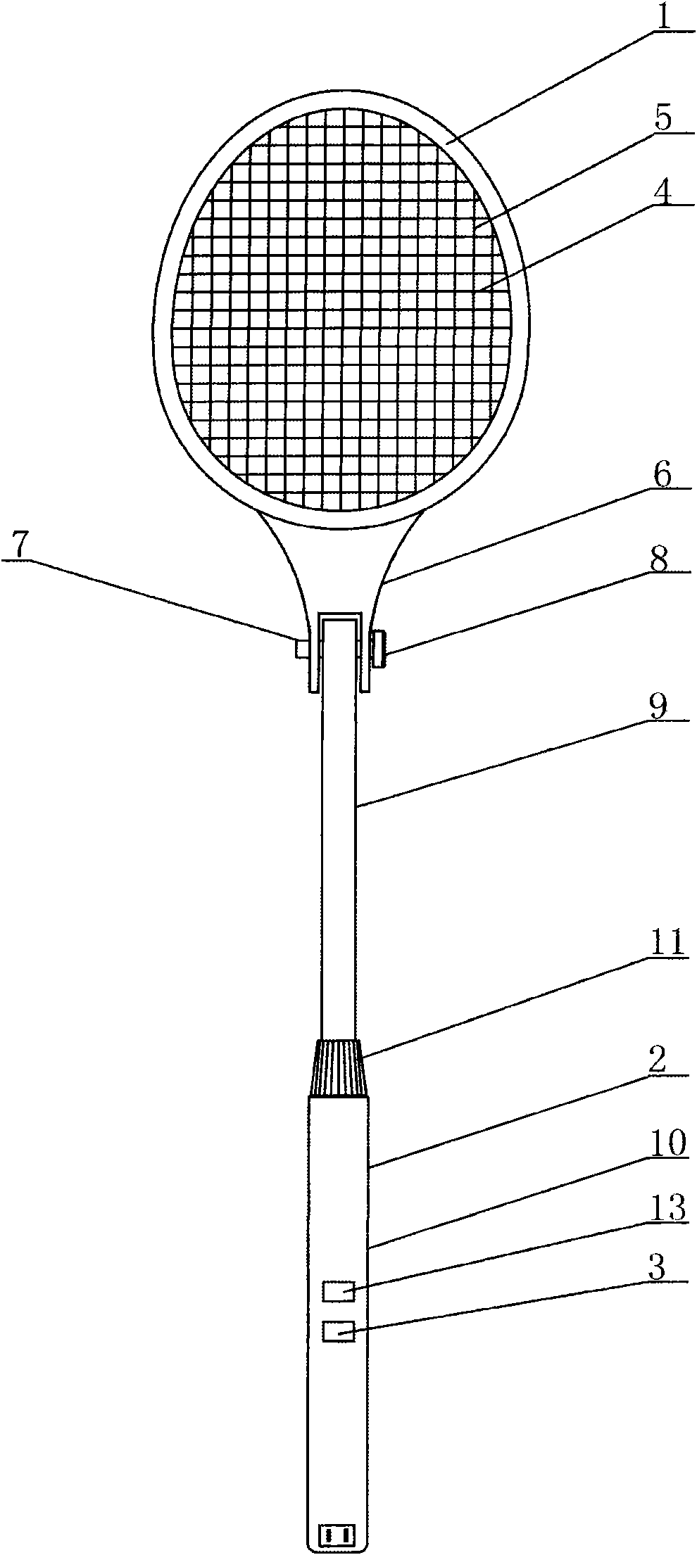
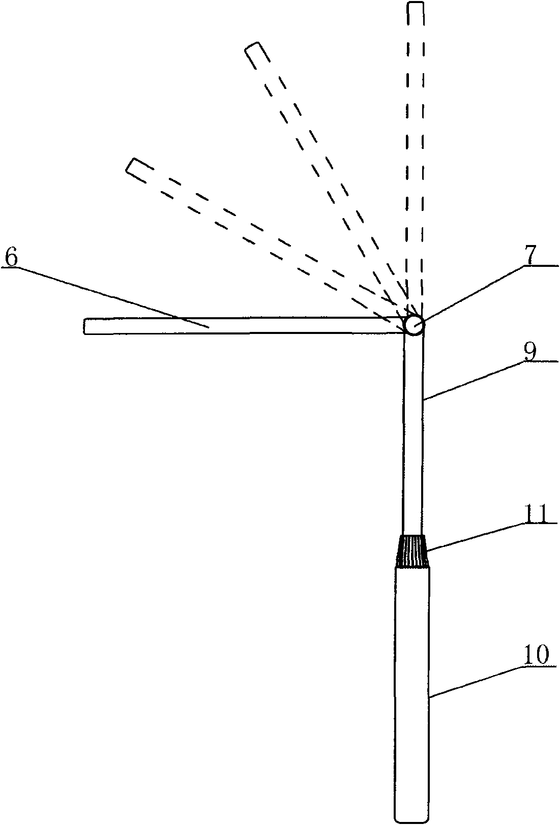
[0022] Such as figure 1 and image 3 As shown, this multifunctional electric mosquito fly swatter includes a racket frame 1, a telescopic rod 2, a boost circuit, a power supply, a switch 3, a plurality of positive electrode wires 4, a plurality of negative electrode wires 5, an extension part of the racket frame 6, a screw rod 7 and nut 8; the boost circuit, power supply and switch 3 are all arranged on the telescopic rod 2; the positive electrode wire 4 and the negative electrode wire 5 are arranged crosswise in the racket frame 1 and pass through the lead wire and the boost circuit, switch 3, Power supply connection, there is a gap between the positive electrode wire 4 and the negative electrode wire 5; the racket frame extension part 6 is provided with a groove, and both sides of the groove of the racket frame extension part 6 and one end of the telescopic rod 2 are provided with through holes, so that the telescopic The end of the rod 2 is in the groove, the screw rod 7 i...

Embodiment approach 2

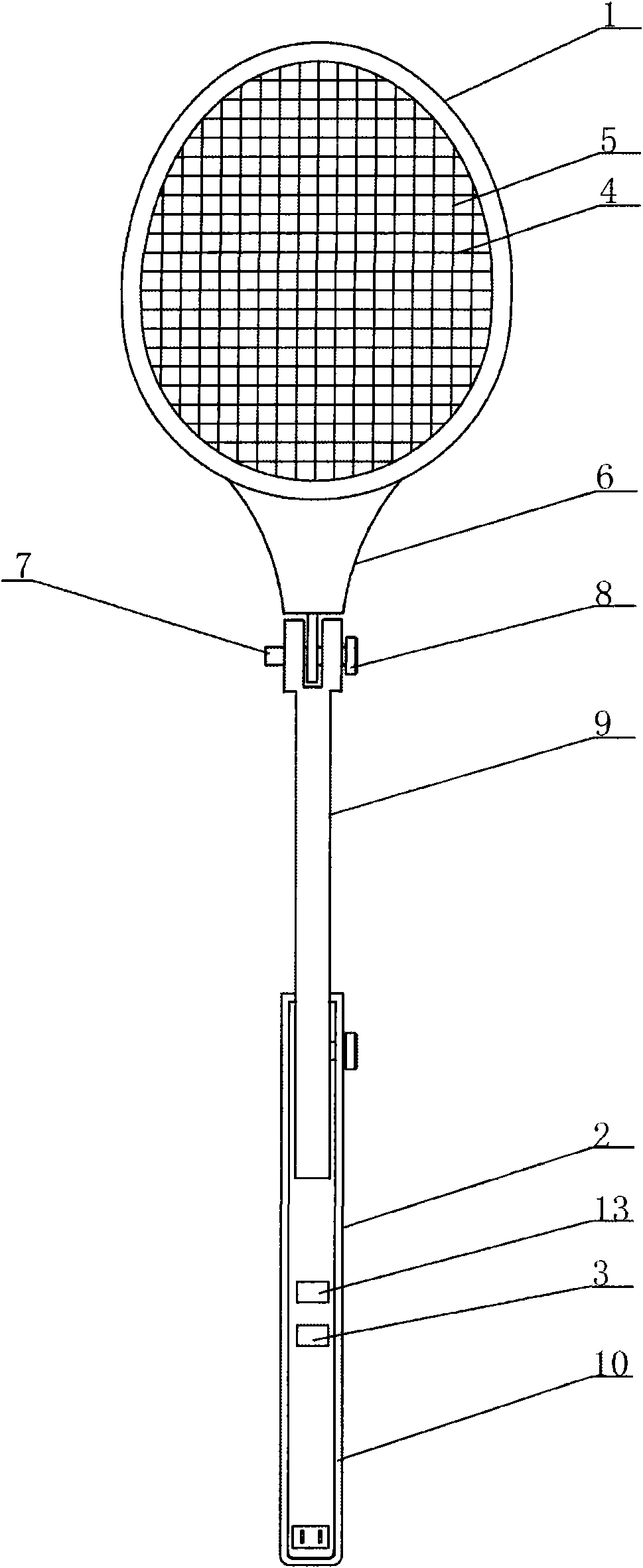
[0026] Such as figure 2 As shown, in the case that other parts are the same as Embodiment 1, the difference is that: the groove is opened at the end of the telescopic rod 2, and the frame extension part 6 is in the groove; the telescopic rod 2 is not connected by a telescopic fixed sleeve , but the outer rod 10 is provided with screw holes communicating with the inner and outer surfaces of the cavity, and the inner rod 9 and the outer rod 10 are fixed by screws 15 .

[0027] In other embodiments, a turning joint is used to connect the extension part of the racket frame and the racket shaft to achieve the purpose of being bendable.


PUM


Abstract

The invention relates to a multifunctional electric mosquito-fly-flap, which comprises a flap frame, a flap rod, a voltage boosting circuit, a power supply, a switch, a plurality of positive electrode wires and a plurality of negative electrode wires and is characterized by also comprising a flap frame extending part, screw rods and screw nuts, wherein the flap rod comprises a telescopic rod, the flap frame extending part and one end of the telescopic rod are respectively provided with through holes, the screw rods are positioned in the through holes of the flap frame extending part and the telescopic rod, and the tail ends of the screw rods are engaged with the screw nuts. Through the arrangement of the telescopic rod and a structure capable of being bent in such a way, the electric mosquito-fly-flap can be used for flapping mosquitoes and flies far away from the ground, in addition, the mosquitoes and the flies staying on a ceiling can also be flapped, simplicity, convenience and practicability are realized, the reinforcing effect is realized on the folding and bending connection through the arrangement of the concave structure, and a light emitting diode is further installed, so moth type small flies such as the mosquitoes and the like can be automatically trapped.

Description

technical field [0001] The invention relates to an electric mosquito swatter, in particular to a multifunctional electric mosquito swatter. Background technique [0002] At present, the electric mosquito swatters sold on the market generally include a racket frame, a racket rod, a booster circuit, a power supply, a switch, a plurality of positive electrode lines and a plurality of negative electrode lines; the booster circuit, power supply and switch are all arranged in On the racket; the positive electrode wire and the negative electrode wire are arranged crosswise in the racket frame to form an electrode network. There is a gap between the positive electrode wire and the negative electrode wire. The leads of the positive electrode wire and the negative electrode wire pass through the booster circuit and the switch Connect the positive and negative poles of the power supply respectively; the racket rod is connected with the racket frame. When in use, turn on the switch to ...

Claims


Application Information

Patent Timeline
IPC IPC(8): A01M3/02A01M1/04A01M1/22
Inventor 魏向颖张少英
Owner 魏向颖
Learn More