Split type occipital plate

A split, occipital technology, applied in the directions of outer plate, inner bone synthesis, fixator, etc., can solve the problems of easy falling off of occipital plate, complicated operation process, difficult fixation, etc., to reduce the risk of slippage, convenient operation, Reduce the effect of strict requirements

Active Publication Date: 2014-07-30
纳通生物科技(北京)有限公司 +1
View PDF5 Cites 0 Cited by
  • Summary
  • Abstract
  • Description
  • Claims
  • Application Information

AI Technical Summary

Problems solved by technology

[0003] 1. The operation process is complicated: due to the integrated structure of the occipital steel plate, when one side of the orthopedic rod fixed on both sides of the occipital steel plate is fixed, the other side tends to warp and is difficult to fix; in addition, although the orthopedic rod has Pre-bending, but due to individual differences in the occipital bone, the pre-bending radian often does not match the occipital radian enough, which further increases the difficulty of operation;
[0004] 2. The occipital plate is easy to fall off after the operation: because the screws fastening the occipital plate are held on one plate and the position is close, stress concentration is prone to occur at the fastening place of the screw, which leads to the screw falling out of the occipital bone and the problem of the occipital plate falling off.
[0005] 3. If figure 1 As shown, the screws on the occipital plate 7 are vertically implanted into the occipital bone 5. During the process of using the tool 21 to implant the screws into the occipital bone 5, there is often interference with the back 20 muscles and soft tissues, and the doctor’s line of sight will be blocked during the operation, resulting in Difficulty in screw placement and difficult fixation

Method used


Image

  • Split type occipital plate
  • Split type occipital plate
  • Split type occipital plate

Examples


Embodiment Construction

[0028] Typical embodiments embodying the features and advantages of the present invention will be described in detail in the following description. It should be understood that the present invention is capable of various changes in different embodiments without departing from the scope of the present invention, and that the description and drawings therein are illustrative in nature and not limiting. this invention.

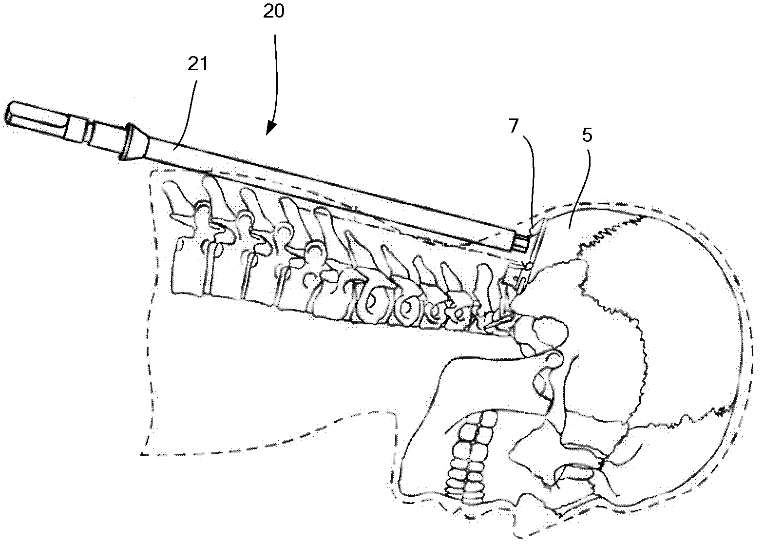
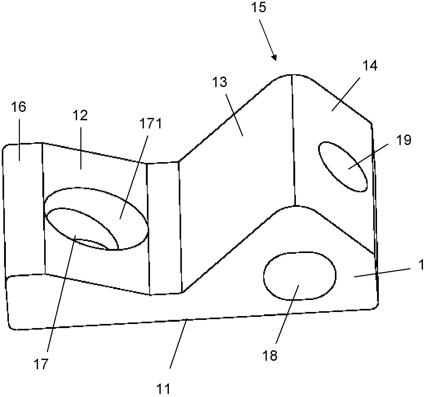
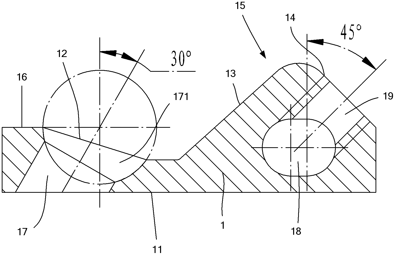
[0029] Such as figure 2 and image 3 As shown, the present invention includes a body 1, and the body 1 is made of titanium alloy or medical stainless steel. The lower end surface of the body 1 is the attachment surface 11 attached to the occipital bone 5 of the human body, which can be a plane, or an irregular surface composed of multiple planes or curved surfaces adapted to the anatomical structure of the human body, or a certain arc can be processed as required shape. The upper end surface of the body 1 can be a plane, or an irregular plane composed of a p...


PUM


Abstract

The invention discloses a split type occipital plate which comprises plate bodies, wherein the lower part of each plate body is an attaching surface used for being attached to an occipital bone of a human body; one side of each plate body is provided with a locking hole, and the other side of each plate body is provided with a stick-passing hole; the other side of each plate body is also provided with a stick-locking hole, and the stick-passing holes are communicated with the stick-locking holes; and the locking holes are through holes passing through the attaching surfaces. According to the invention, 2-4 separately-processed occipital plate bodies are adopted and used in pairs, respective orthopedic sticks of the occipital plate bodies used in pairs in the process of fixing orthopedic sticks can be fixed separately and respectively, the fixed position is adjusted conveniently, and the operation is convenient and rapid.

Description

technical field [0001] The invention relates to an auxiliary device for posterior cervical occipital fusion, in particular to an occipital bone plate. Background technique [0002] At present, for traumatic cervical fractures, especially fractures in the cervical region, occipitocervical fusion is often used to fix the fracture end. The occipital-cervical fixation system in the prior art often uses an integrated occipital bone plate and orthopedic rods for fixation. This is clinically There are many problems, such as: [0003] 1. The operation process is complicated: due to the integrated structure of the occipital steel plate, when one side of the orthopedic rod fixed on both sides of the occipital steel plate is fixed, the other side tends to warp and is difficult to fix; in addition, although the orthopedic rod has Pre-bending, but due to individual differences in the occipital bone, the pre-bending radian often does not match the occipital radian enough, which further i...

Claims


Application Information

Patent Timeline
Patent Type & Authority Patents(China)
IPC IPC(8): A61B17/80
Inventor 石志才郑卜纵闫寒冰张勋
Owner 纳通生物科技(北京)有限公司
Why Eureka
Try Eureka