Automatic precision net puller

A precision stretching machine and frame technology, applied in the field of stretching machines, can solve the problems of affecting efficiency, waste of mesh cloth, unqualified mesh cloth, etc., and achieve the goal of improving production efficiency, avoiding loosening, and good clamping and fixing effect Effect

Active Publication Date: 2012-06-13
GUANGDONG YINCAI TECH CO LTD
View PDF6 Cites 9 Cited by
  • Summary
  • Abstract
  • Description
  • Claims
  • Application Information

AI Technical Summary

Problems solved by technology

Existing stretching machines for stretching mesh cloth generally include a body, a screw rod displacement mechanism and a stretching chuck, and the stretching chucks all adopt independent chucks, and a plurality of independent chucks are arranged side by side around the body. The displacement mechanism can use a variety of transmission methods to achieve displacement, but the movements between the screw displacement mechanisms on each side are independent of each other, and they all move longitudinally along the length direction. The periphery of the cloth is clamped, and then driven by the displacement mechanism to stretch outwards to make the mesh tight; however, the stretching machine with the above structure has the following disadvantages: (1) because the stretching clips on each outer periphery of the body The head system is composed of multiple independent chucks, and it is easy to cause uneven tension of the mesh between the chucks, causing the warp and weft of the mesh to not be perpendicular to each other, making a large part of the stretched mesh unqualified , Moreover, there are many independent chucks on each outer periphery of the body, which is extremely troublesome to operate, which not only affects the efficiency, but also easily damages one of the chucks, resulting in the defect that the whole machine cannot be used; (2) the mesh The four corner ends will be deformed by the uneven tension and relaxation of the adjacent screw displacement mechanism when pulling the net, making the four corners discarded and unusable, resulting in a waste of mesh

Method used


Image

  • Automatic precision net puller
  • Automatic precision net puller
  • Automatic precision net puller

Examples


Embodiment Construction

[0019] The invention will be described in further detail below in conjunction with the accompanying drawings.

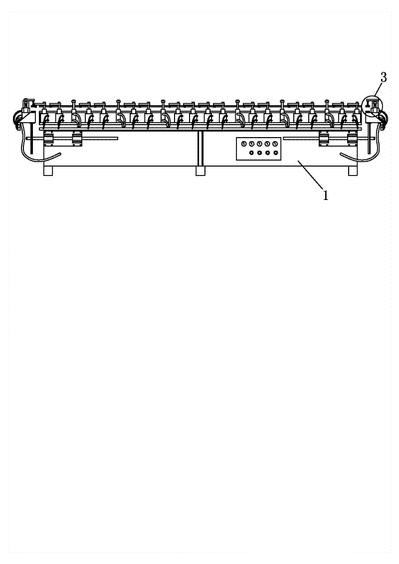
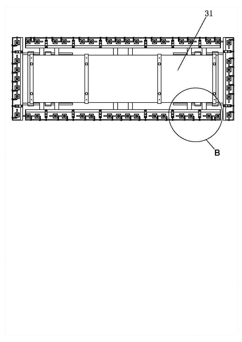
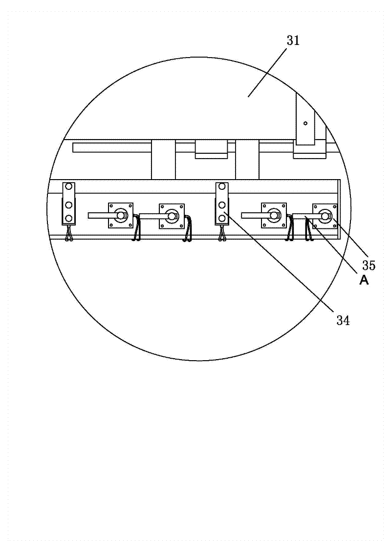
[0020] like Figure 1 to Figure 5 As shown, a kind of automatic precision stretching machine includes a frame 1 and a wire mesh chuck mechanism 3 installed on each outer periphery of the frame 1. It is characterized in that the wire mesh chuck mechanism 3 is mainly composed of a moving seat 31 , bottom plate 32, splint 33, lifting cylinder 34 and rotary cylinder 35, the moving seat 31 is installed on the outer periphery of the frame 1 in a slidable manner through the guide rail, and the side of the moving seat 31 near the outer periphery of the frame 1 is fixed with a bottom plate 32. Lifting cylinder 34 and rotating cylinder 35 are respectively installed on the mobile seat 31 next to the base plate 32. The lifting end of the lifting cylinder 34 is connected to the splint 33, and the splint 33 is located above the base plate 32. Head, the rotating end A of the rotat...


PUM


Abstract

The invention relates to an automatic precision net puller which comprises a stand and silk net chuck mechanisms arranged at the peripheries of the stand, wherein each silk net chuck mechanism mainly comprises a movable seat, a base plate, a clamping plate, a lifting air cylinder and a rotating air cylinder; the movable seat is arranged at the periphery of the stand through a guide rail in a slidable manner; the base plate is fixedly arranged at one side of the movable seat, which is close to the periphery of the stand; the lifting air cylinder and the rotating air cylinder are respectively arranged on the movable seat besides the base plate; a lifting end of the lifting air cylinder is connected with the clamping plate; the clamping plate is positioned above the base plate and forms a chuck of a silk net together with the base plate; and a rotating end of the rotating air cylinder is supported against the clamping plate so as to pressurize the clamping plate. The automatic precision net puller has the advantages of reasonable structure, simpleness and easiness for operation and better tightening effect of mesh.

Description

technical field [0001] The invention relates to the technical field of stretching machines, in particular to an automatic precision stretching machine. Background technique [0002] In the field of screen printing, the quality of the screen directly affects the printing quality. Existing stretching machines for stretching mesh cloth generally include a body, a screw rod displacement mechanism and a stretching chuck, and the stretching chucks all adopt independent chucks, and a plurality of independent chucks are arranged side by side around the body. The displacement mechanism can use a variety of transmission methods to achieve displacement, but the movements between the screw displacement mechanisms on each side are independent of each other, and they all move longitudinally along the length direction. The periphery of the cloth is clamped, and then driven by the displacement mechanism to stretch outwards to make the mesh tight; however, the stretching machine with the ab...

Claims


Application Information

Patent Timeline
Patent Type & Authority Applications(China)
IPC IPC(8): B41F15/34
Inventor 刘健
Owner GUANGDONG YINCAI TECH CO LTD
Why Eureka
Try Eureka