Method for correcting position during the glass grabbing process of manipulator of manipulator glass stacking system

A calibration method and manipulator technology, which are applied in the stacking of objects, destacking, transportation and packaging of objects, etc., can solve the problems of short service life, high cost, deviation speed of the roller table, etc., and achieve long service life and maintenance. Convenient and low-cost effect

Active Publication Date: 2015-01-07
CHINA TRIUMPH INT ENG
View PDF6 Cites 0 Cited by
  • Summary
  • Abstract
  • Description
  • Claims
  • Application Information

AI Technical Summary

Problems solved by technology

[0003] However, the instruction for the manipulator to grab the moving glass from the roller table comes from the management system or the host computer or wire control, because the position where the manipulator grabs the glass is not the same as the position where the management system obtains the glass position value, that is, the position obtained by the manipulator The value is converted by the management system according to the position of the manipulator and the speed of the roller table; between these two points, due to the deviation of the roller table and the uneven speed, when the glass moves to the grabbing position of the manipulator, its position value is the same as that of the management system. The values ​​provided are inconsistent; when the error is large, it is easy to cause the vacuum gripper on the manipulator to grab the glass, resulting in stacking failure; The position changes greatly, but the trajectory of the manipulator is fixed, which will cause interference and collision between the glass and the manipulator or other equipment. Therefore, the existing technology has low accuracy of data capture, high cost, troublesome installation and long service life. short

Method used


Image

  • Method for correcting position during the glass grabbing process of manipulator of manipulator glass stacking system
  • Method for correcting position during the glass grabbing process of manipulator of manipulator glass stacking system
  • Method for correcting position during the glass grabbing process of manipulator of manipulator glass stacking system

Examples


Embodiment Construction

[0013] The invention is described in further detail below in conjunction with the accompanying drawings. This manufacturing technology is clear to those in the field.

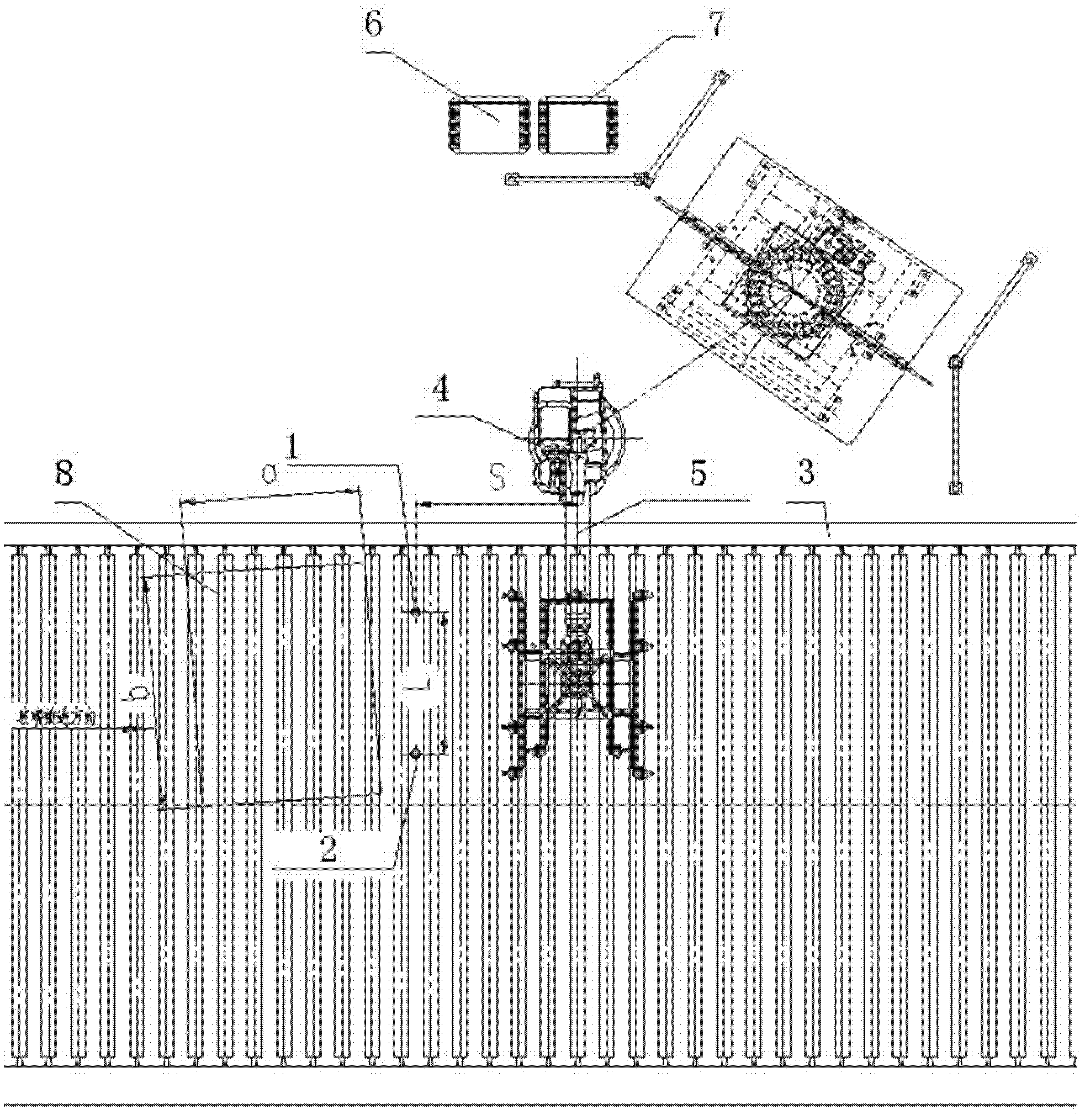
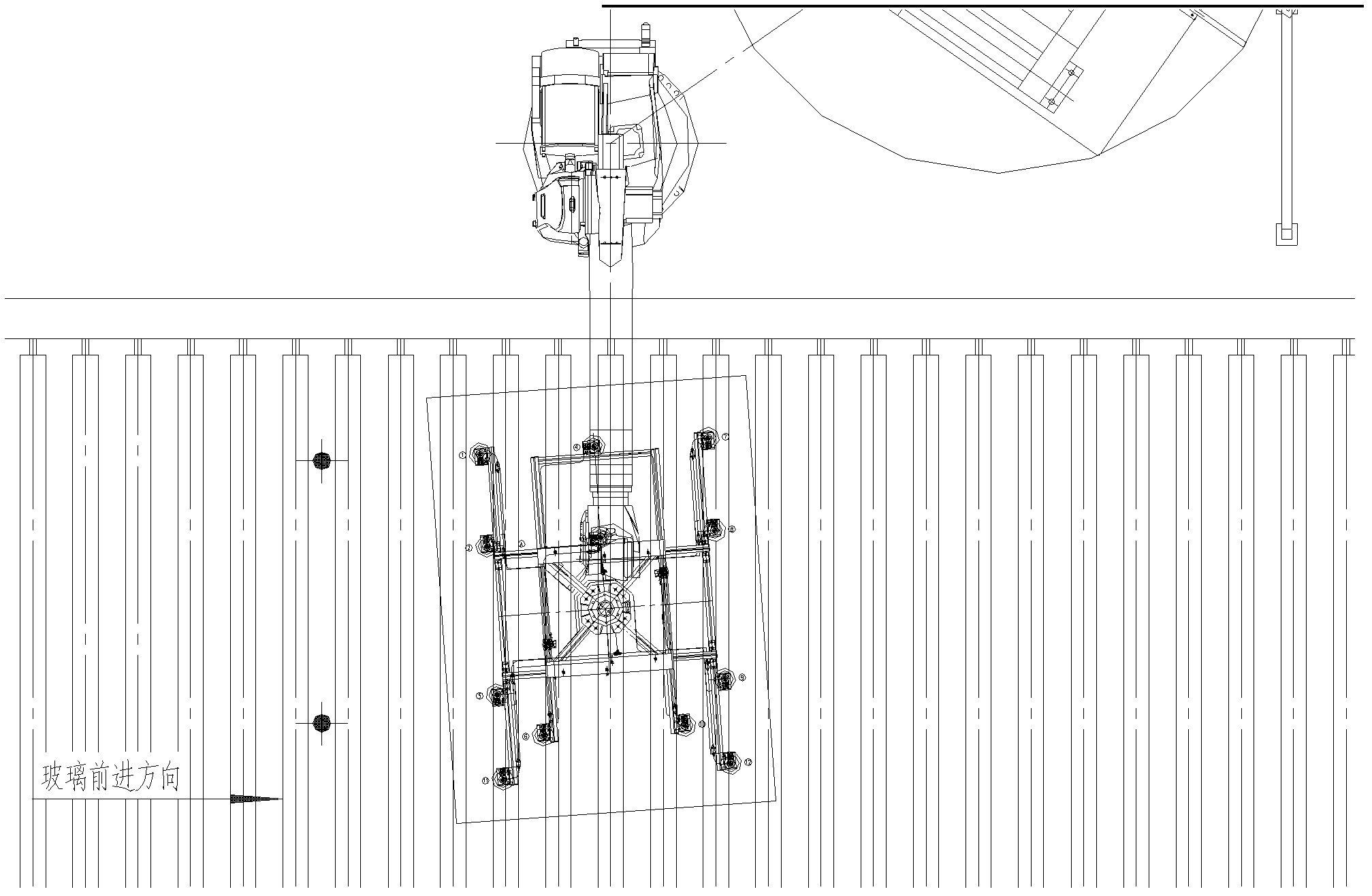
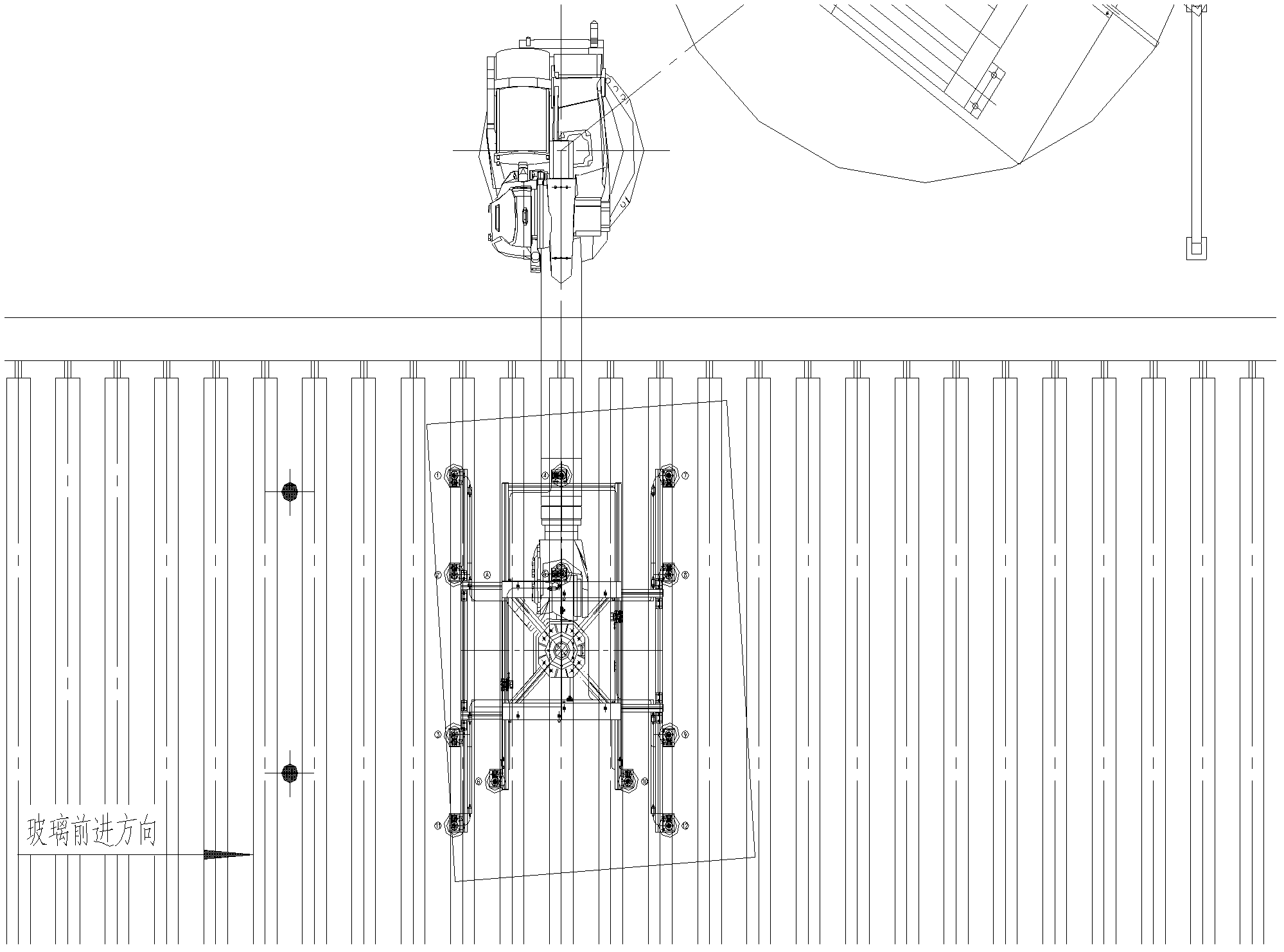
[0014] Such as figure 1 , figure 2 with image 3 As shown, the photoelectric sensor I and the photoelectric sensor II are installed at the upstream S of the manipulator center. The distance between the two photoelectric sensors is L (1.5m, the specific size can be adjusted according to the actual situation), and the photoelectric sensor is connected to the control cabinet (PLC) of the manipulator. When the glass passes the photoelectric sensor: the photoelectric sensor senses the edge of the glass and sends out a signal. The size of the glass is axb (length x width). The photoelectric sensor signal is connected to the control system, and the deflection value and the grabbing time point are processed by the PLC and provided to the manipulator control system.

[0015] The deflection angle, when the glass is skewed,...


PUM


Abstract

The invention relates to the technical field of a manipulator glass stacking system, in particular to a method for correcting a position during the glass grabbing processing of a manipulator of the manipulator glass stacking system. A photoelectric sensor I and a photoelectric sensor II are arranged between two rollers which are arranged at the upstream of a roller bed which keeps a distance s away from the center of the manipulator, the distance between the photoelectric sensor I and the photoelectric sensor II is 1-1.5m, dimension of the glass is a*b or length*width, v is the speed of the roller bed, when the glass deflects, time t1 for the photoelectric sensor I to send a signal and the time t2 for the photoelectric sensor II to send a signal are different, is adopted: a deflection angle is acquired according to the following computational formula: deflection angle &=(t1-t2)*v / 1; and a time point of grabbing is calculated according to the formula that t=tn+(S-|t1-t2|*v / 2) / v+a / 2 / v, wherein tn is a greater time point in t1 and t2. The method provided by the invention has the advantages of convenience in installation, low cost, long service life and convenience in maintenance.

Description

[Technical Field] [0001] The invention relates to the technical field of a manipulator glass stacking system, in particular to a method for correcting the position of the manipulator glass stacking system when the manipulator grabs glass. [Background technique] [0002] Manipulator glass stacking system is one of the special equipment for stacking glass production line. During the stacking process, there is no need to stop the board, the operation is stable, the precision is high, the cycle is short, and the degree of automation is high. Each manipulator can correspond to multiple stations. One manipulator can stack different specifications or grades of glass. The glass industry is increasingly widely used. [0003] However, the manipulator's instruction to grab the moving glass from the roller table comes from the management system or the host computer or wire control. Because the position where the manipulator grabs the glass and the position where the management system obtains ...

Claims


Application Information

Patent Timeline
Patent Type & Authority Patents(China)
IPC IPC(8): B65G61/00
Inventor 刘晓亮王川申张荣松韩德刚张红明顾丽琴刘路明
Owner CHINA TRIUMPH INT ENG
Why Eureka
Try Eureka