
Method and system for controlling rotation of cranes

Active Publication Date: 2014-07-09
ZOOMLION HEAVY IND CO LTD
View PDF5 Cites 0 Cited by
  • Summary
  • Abstract
  • Description
  • Claims
  • Application Information

AI Technical Summary

Problems solved by technology

However, how to reduce the impact of the kinetic energy of the hoisted object on the stability of the crane has not yet been proposed in the related art.

Method used


Image

  • Method and system for controlling rotation of cranes
  • Method and system for controlling rotation of cranes
  • Method and system for controlling rotation of cranes

Examples


Embodiment Construction

[0031] It should be noted that, in the case of no conflict, the embodiments in the present application and the features in the embodiments can be combined with each other. The present invention will be described in detail below with reference to the accompanying drawings and examples.

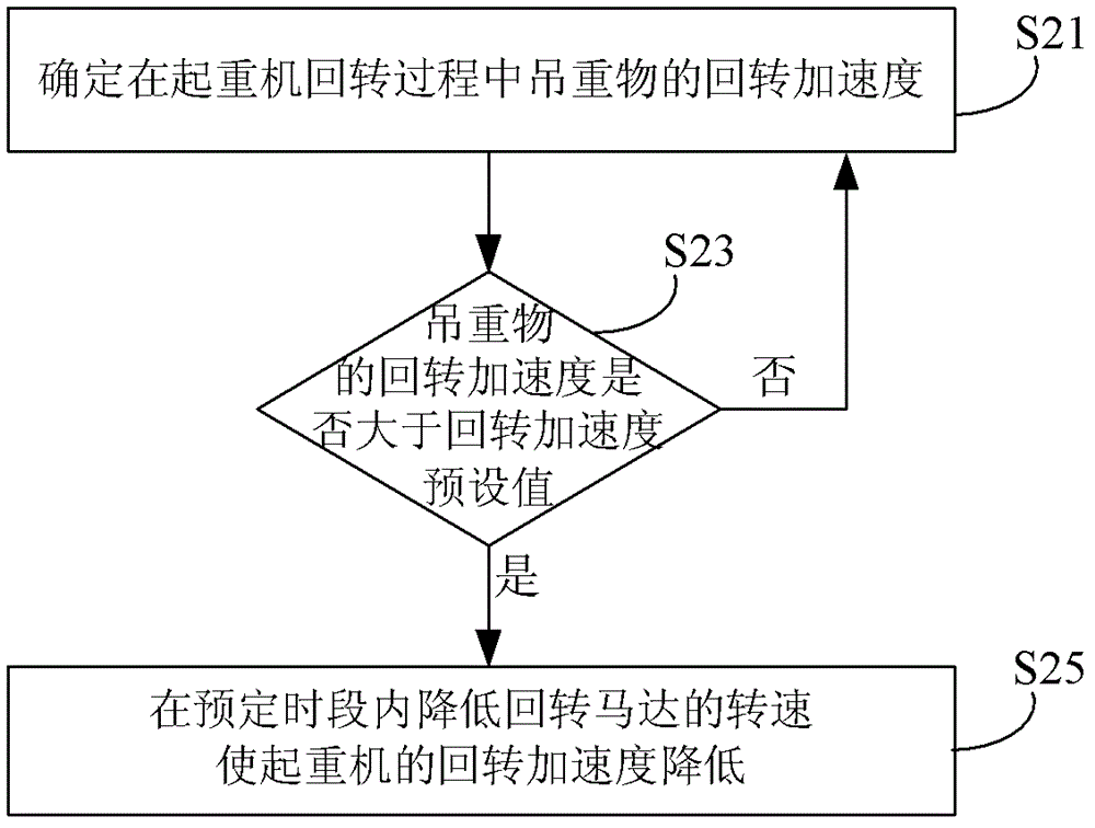
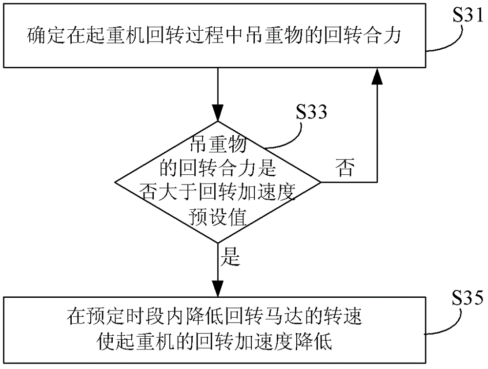
[0032] In this embodiment, the rotational speed of the slewing motor is controlled by judging whether the slewing acceleration or the resultant slewing force of the hoisted object is greater than a preset value during the slewing of the crane, and then the speed of the slewing motor is reduced within a set period of time so that the crane's The slewing acceleration is reduced. The basic process can be used in detail figure 2 or image 3steps shown.

[0033] figure 2 It is a schematic diagram of the basic steps of the crane slewing control method according to the embodiment of the present invention, such as figure 2 As shown, it mainly includes the following steps:

[0034] Step S21: De...


PUM


Abstract

Disclosed are a method and a system for controlling crane rotation. The method and the system comprise: determining the rotational acceleration or resultant rotational force of the pendant ballast when the crane is rotating (S31); when the rotational acceleration is greater than a preset value thereof, or when the resultant rotational force is greater than a preset value thereof (S33), reducing the rotary speed of the rotational motor within a determined time period so as to reduce the rotational acceleration of the crane (S35). Using the method and the system aids in preventing the destructive influence of the kinetic energy of the pendant ballast on the overall or partial stability of the crane.

Description

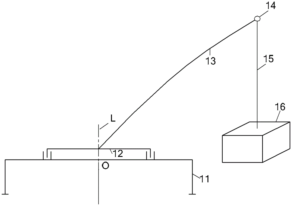
technical field [0001] The invention relates to the technical field of engineering machinery control, in particular to a method and system for crane slewing control. Background technique [0002] Crane is a kind of common engineering machinery, which has a slewing platform and a lifting device, which can lift heavy objects to a certain height to meet the needs of engineering construction. A simplified structure of the crane in the prior art is as figure 1 as shown, figure 1 It is a schematic diagram of a simplified structure of a crane according to the prior art. [0003] figure 1 The supporting legs 11 of the crane, the slewing platform 12, the boom 13, the boom head 14, the sling 15 connected between the boom head and the weight are shown in the figure, and the hoisting weight 16 is also shown. During the slewing process, the slewing platform rotates around a straight line L which is perpendicular to the slewing plane and passes through the slewing center O of the slew...

Claims


Application Information

Patent Timeline
Patent Type & Authority Patents(China)
IPC IPC(8): B66C13/22B66C23/84
CPCB66C13/30B66C13/06
Inventor 詹纯新刘权张建军李义李英智郭纪梅
Owner ZOOMLION HEAVY IND CO LTD
Learn More