Variable angle coupling mechanism

A technology of connecting mechanism and changing angle, applied in the direction of building components, building structures, walls, etc., can solve problems such as construction design is difficult to achieve, and achieve the effect of eliminating mutual restraint and welding stress, small error, and wide practical value.

Active Publication Date: 2014-02-26
SHENZHEN SANXIN FACADE ENG
View PDF2 Cites 0 Cited by
  • Summary
  • Abstract
  • Description
  • Claims
  • Application Information

AI Technical Summary

Problems solved by technology

The original construction design is difficult to achieve

Method used


Image

  • Variable angle coupling mechanism
  • Variable angle coupling mechanism
  • Variable angle coupling mechanism

Examples


Embodiment Construction

[0049] In order to fully understand the technical content of the present invention, the technical solutions of the present invention will be further introduced and illustrated below in conjunction with specific examples, but not limited thereto.

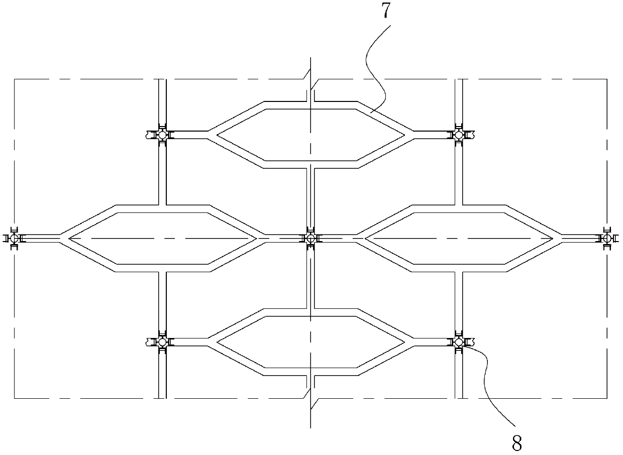
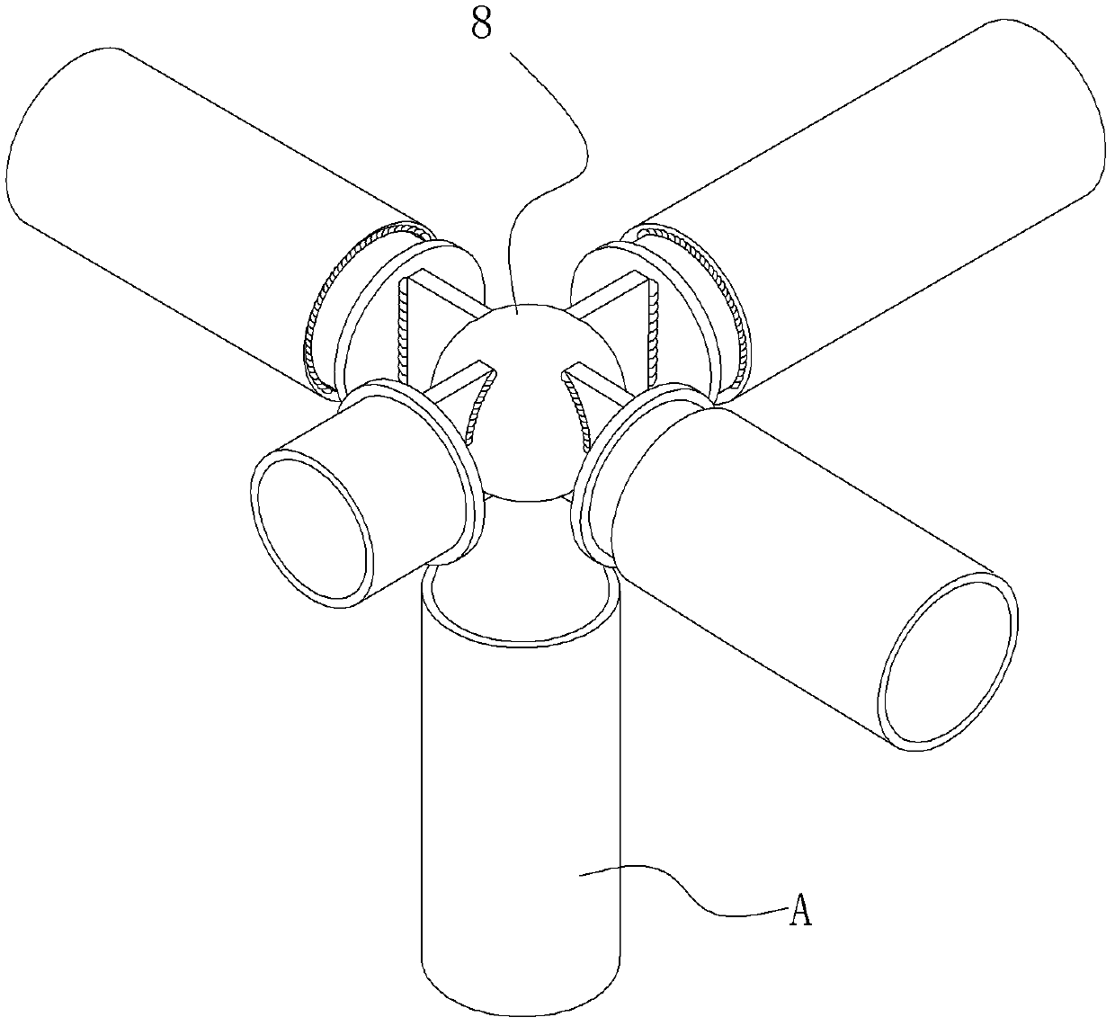
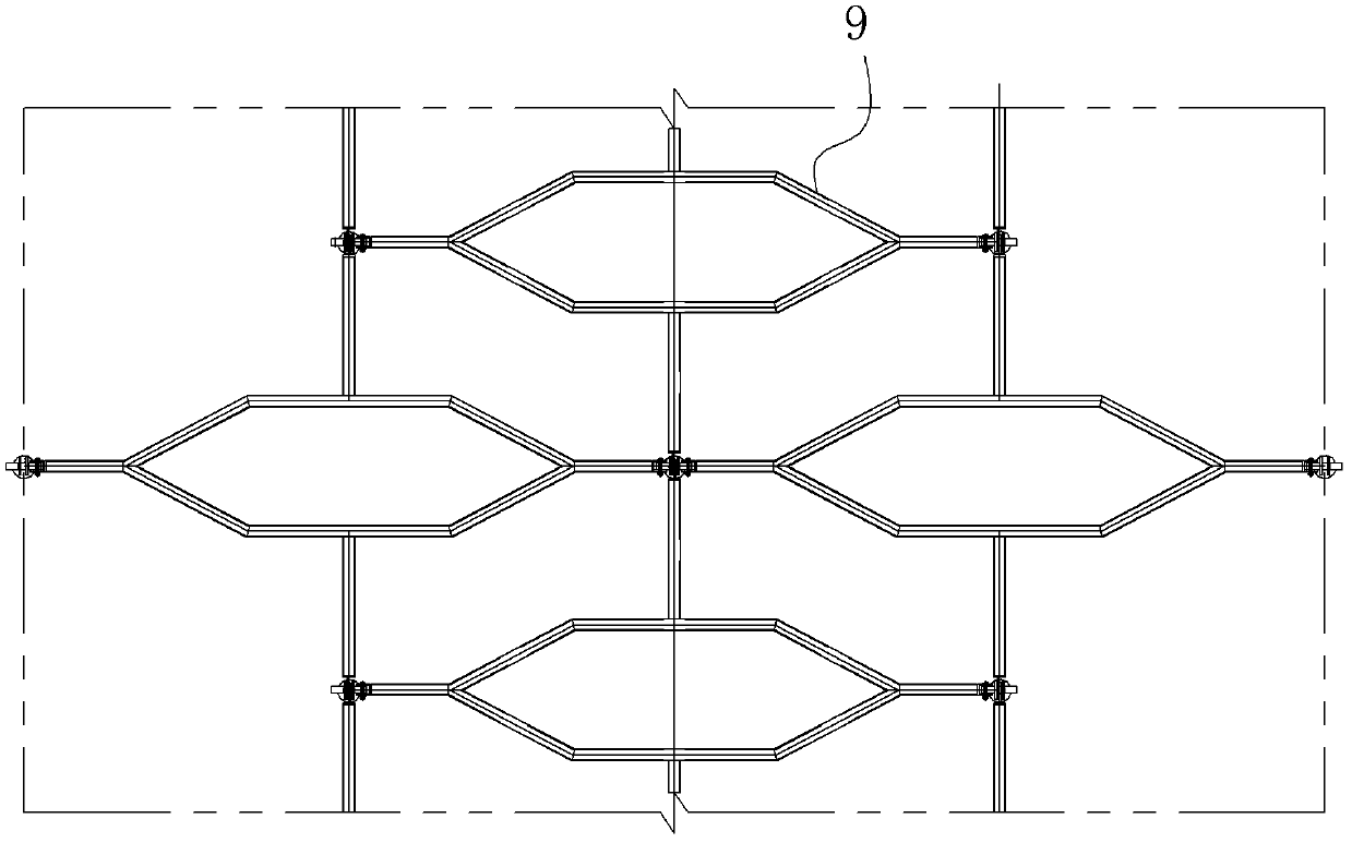
[0050] Such as Figure 3 to Figure 11As shown, a variable-angle coupling mechanism of the present invention includes a base 1 fixedly coupled to the main body structure (i.e., the support rod A), and a first coupling 21, a second coupling 22, and a third coupling connected to the base 1 23. The fourth coupling piece 24. The base 1 includes a bottom plate 11, two support plates 12A, 12B arranged above the bottom plate 11, and a central shaft 3 connected with the two support plates 12A, 12B. The first coupling piece 21, The second coupling part 22 is hingedly connected with the central shaft 3; the inner ends of the first coupling part 21 and the second coupling part 22 are respectively provided with a first hinged hole 210 and a secon...


PUM


Abstract

The invention discloses a variable angle coupling mechanism, which comprises a base fixedly coupled with a main body structure, as well as a first coupling piece, a second coupling piece, a third coupling piece and a fourth coupling piece that are coupled with the base, wherein the base includes a base plate, two support plates arranged above the base plate, as well as a central shaft coupled with the two support plates; the first coupling piece and the second coupling piece are hinged with the central shaft; the inner ends of the first coupling piece and the second coupling piece are respectively provided with a first hinge hole and a second hinge hole that are hinged with the central shaft; and both ends of the central shaft are respectively provided with a right coupling hole hinged with the third coupling piece and a left coupling hole hinged with the fourth coupling piece. The four coupling pieces provided by the invention all can form certain angular deflections with the base and reserve movement allowances; when the spherical surface coupling structure is adopted, the base can also be used for coupling two coupling pieces mutually inclined for a certain grade; moreover, in the invention, the conventional welding node is replaced by purely mechanical connection, so that the installation location is accurate and the error is small.

Description

technical field [0001] The invention relates to a fixed connection mechanism for building curtain walls, in particular to a variable-angle connection mechanism for interconnecting unitized curtain wall steel structures (or aluminum structures). Background technique [0002] The roof of the original construction design of an airport terminal has a curtain wall support structure system composed of honeycomb steel structure parts on the side. Each pole of the honeycomb steel structure part is equipped with an adjustment sleeve on site, and four honeycomb steel structure A support rod (four in total) in the component is welded to a spherical joint to form the roof and the curtain wall support structure system on both sides (such as figure 1 , figure 2 shown). [0003] There are more than 120 kinds of honeycomb steel structures with the same size and a large number, and the total number is more than 11,000, which are called standard types; there are more than 5,000 honeycomb s...

Claims


Application Information

Patent Timeline
Patent Type & Authority Patents(China)
IPC IPC(8): E04B2/88
Inventor 张桂先花定兴左晓韩东龙榕恒
Owner SHENZHEN SANXIN FACADE ENG
Why Eureka
Try Eureka