AI technical title is built by PatSnap AI team. It summarizes the technical point description of the patent document.
A light steel structure and construction technology, applied in the direction of buildings, roofs, building components, etc., can solve the problems of delayed construction period, easy damage, long construction time, etc.
Inactive Publication Date: 2012-06-13
ANHUI WATER RESOURCES DEV
View PDF6 Cites 7 Cited by
Summary
Abstract
Description
Claims
Application Information
AI Technical Summary
This helps you quickly interpret patents by identifying the three key elements:
Problems solved by technology
Method used
Benefits of technology
Problems solved by technology
The disadvantages of this construction method are: the construction time is long, the construction period is easy to be delayed, the struts and formwork are easily damaged after being used several times, and materials are wasted
The defect of the roof is: there is an obvious beam-column structure, which affects the appearance, and is not suitable for large-span buildings
The disadvantages of this roof are: easy to leak water, poor thermal insulation effect, and the underside of the roof is not beautiful
Method used
Image
Click on the blue label to locate the original text in one second.
Reading with bidirectional positioning of images and text.
Examples
Embodiment 1
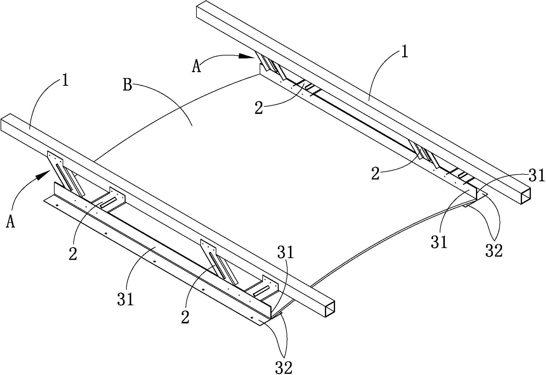
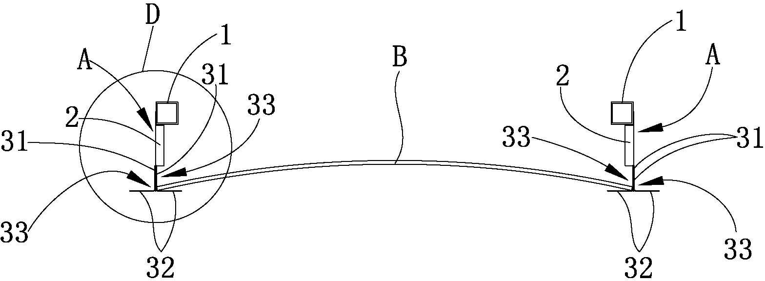
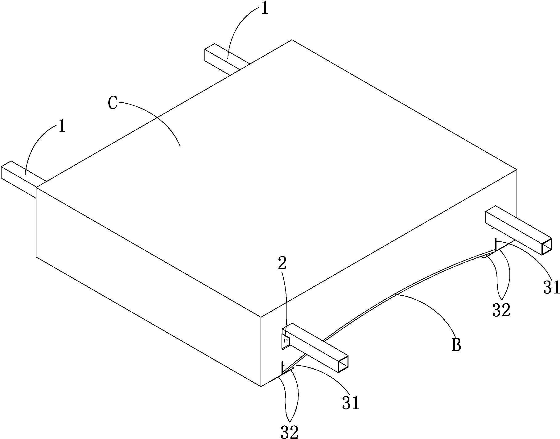
[0033] see figure 1 — Figure 4 :
[0034] The roof consists of several vertical trusses A parallel to each other, an arched plate B connected between the lower ends of every two adjacent trusses A, containing every two adjacent trusses A and the arched plate B between them The covering layer C.
[0035] For the sake of succinct explanation, figure 1 , figure 2 , image 3 Only two vertical trusses A and one arched plate B are shown in . The two trusses A can be of corresponding length according to design requirements, and then overlapped on the walls or structural beams on both sides of the house (the walls or structural beams are not shown in the drawings).
[0036] Each truss A includes a horizontal upper tube 1, two vertical V-shaped connectors 2, two horizontal L-shaped lower angle steels symmetrically located below the upper tube 1 and parallel to the upper tube 1;
[0037] The two vertical wing plates 31 of the two lower angle steels are spaced in parallel, and t...
Embodiment 2
[0045] see Figure 5 — Figure 8 :
[0046] The roof consists of several vertical trusses A parallel to each other, an arched plate B connected between the lower ends of every two adjacent trusses A, containing every two adjacent trusses A and the arched plate B between them The covering layer C.
[0047] For the sake of succinct explanation, Figure 5 , Figure 6 , Figure 7 Only two vertical trusses A and one arched plate B are shown in . The two trusses A can be of corresponding length according to design requirements, and then overlapped on the walls or structural beams on both sides of the house (the walls or structural beams are not shown in the drawings).
[0048] Each truss A includes a horizontal upper pipe 1, several vertical V-shaped connectors 2, a downward extending horizontal sword-shaped angle steel below the upper pipe 1 and parallel to the upper pipe 1;
[0049] The two inclined wing plates 32 of the sword-shaped angle steel extend outward and are symme...
PUM
Abstract
The invention discloses a lightweight steel construction roof. The lightweight steel construction roof comprises a plurality of vertical trusses which are parallel to each other, arched plates and covering layers, wherein one arched plate is supported and connected between the lower ends of every two adjacent trusses; and each covering layer covers every two adjacent trusses and the arched plate between the two adjacent trusses. Each covering layer is a cement plaster layer which comprises an upper layer and a lower layer, wherein the lower layer is a foam concrete layer or a polyphenyl particle thermal insulationmortar layer, and the upper layer is a concrete layer. Due to the adoption of the structure, each arched plate forms a whole independent plate and is fixed by a supporting and connection structure, so water leakage is avoided on the roof; and each covering layer covers the every two adjacent trusses and the arched plate between the two adjacent trusses, so the roof is good in the thermal insulation effect.
Description
technical field [0001] The invention relates to a light steel structure building roof. Background technique [0002] At present, there are two structural forms of building roofs: reinforced concrete roofs cast on site and steel structure roofs. [0003] The construction method of the reinforced concrete roof cast on site is as follows: use the concrete poured beams and columns as the frame, use wooden struts or steel pipes to temporarily support the formwork, then bind the steel bars between the frame and the formwork, and then pour the concrete between the frame and the formwork After the concrete has gone through the curing period, the struts and formwork are removed to form the roof. The defect of this construction method is: the construction time is longer, and the construction period is easily delayed, and the struts and formwork are easily damaged after being used for several times, which wastes materials. The defect of the roof is that it has an obvious beam-column ...
Claims
Application Information
Patent Timeline
Application Date:The date an application was filed.
Publication Date:The date a patent or application was officially published.
First Publication Date:The earliest publication date of a patent with the same application number.
Issue Date:Publication date of the patent grant document.
PCT Entry Date:The Entry date of PCT National Phase.
Estimated Expiry Date:The statutory expiry date of a patent right according to the Patent Law, and it is the longest term of protection that the patent right can achieve without the termination of the patent right due to other reasons(Term extension factor has been taken into account ).
Invalid Date:Actual expiry date is based on effective date or publication date of legal transaction data of invalid patent.

