High temperature superconducting motor magnet performance test device

A technology of high-temperature superconductivity and test equipment, which is applied in the direction of magnetic performance measurement, measurement equipment, and measurement of electrical variables, to achieve the effects of improving cooling efficiency, convenient installation and wiring of magnets, and authentic and reliable test data

Active Publication Date: 2012-06-13
中国船舶重工集团公司第七一二研究所
View PDF5 Cites 8 Cited by
  • Summary
  • Abstract
  • Description
  • Claims
  • Application Information

AI Technical Summary

Problems solved by technology

[0004] The present invention provides a high-temperature superconducting motor magnet performance test device, which solves the problems of large refrigerant consumption, troublesome test preparation process such as magnet installation and wiring, and Make the magnet cooling method exactly the same as the actual situation, improve the measurement accuracy

Method used


Image

  • High temperature superconducting motor magnet performance test device
  • High temperature superconducting motor magnet performance test device
  • High temperature superconducting motor magnet performance test device

Examples


Embodiment 1

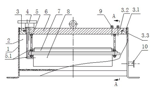
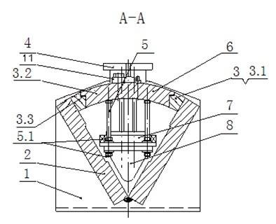
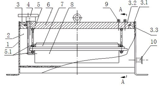
[0022] A high-temperature superconducting motor magnet performance test device, including a magnetically conductive side plate 2 and a magnetically conductive arc top plate 3; the two magnetically conductive side plates 2 form a "V"-shaped angle, and form a magnetically conductive circuit with the magnetically conductive arc top plate 3 ; The magnetic side plate 2, the magnetic arc top plate 3 and the stainless steel end plates 1 at both ends constitute a vacuum container; the stainless steel end plate 1 has a vacuum interface 10; the vacuum container is provided with a heat exchanger 8, the The heat exchanger 8 is connected to the magnetically conductive circular arc top plate 3 through the heat insulating stud 5; the magnetically conductive circular arc top plate 3 is provided with a refrigerant inlet and outlet interface 4 communicating with the refrigerant container or the refrigerator. The magnetically conductive circular arc top plate 3 is composed of a fixed top plate 3....

Embodiment 2

[0024] The difference from the above-mentioned embodiment 1 is that, in the high-temperature superconducting motor magnet performance test device, the refrigerant inlet and outlet ports 4 communicate with the refrigerant container or refrigerator through pipelines. The magnetically permeable side plate 2 is formed by welding two magnetically permeable side plates through the lower part to form a "V" shape structure, or one magnetically permeable side plate is integrally molded into a "V" shaped corner. The magnetically permeable side plate 2, the "V"-shaped corner and the magnetically permeable arc top plate 3 constitute the boundary conditions of the magnetic field, form a magnetically permeable circuit, and simultaneously become a part of the vacuum container shell.


PUM


Abstract

The invention relates to a high temperature superconducting motor magnet performance test device, which comprises magnetic conducting side plates and a magnetic conducting circular arc top plate, wherein the two magnetic conducting side plates form a 'V'-shaped angle and form a magnetic conducting loop with the a magnetic conducting circular arc top plate; the magnetic conducting side plates, the magnetic conducting circular arc top plate and stainless steel end plates on two ends form a vacuum container; vacuum-pumping connectors are arranged on the stainless steel end plates; a heat exchanger is arranged in the vacuum container and is connected with the magnetic conducting circular arc top plate through insulating studs; and the magnetic conducting circular arc top plate is provided with a refrigerant import and export connector communicated with a refrigerant container or a refrigerator. The high temperature superconducting motor magnet performance test device has the advantages that: the problems of larger refrigerant consumption amount, complexity of installation, wiring and other test preparation processes of a magnet, and the like are solved; the cooling method of the magnet is as same as the actual conditions; and the measuring accuracy is improved.

Description

technical field [0001] The invention relates to a high-temperature superconducting motor magnet performance test device, which belongs to the technical field of measurement and testing. Background technique [0002] The high temperature superconducting motor magnet is used as the excitation winding in the motor and is a major component of the high temperature superconducting motor. Under normal circumstances, several superconducting magnets on the rotor are located in a vacuum container formed by welding. Due to the poor mechanical properties of high-temperature superconducting materials, the performance will be greatly reduced if there is a slight carelessness during the processing of the magnets. Therefore, Before the magnet is installed, the performance of the magnet should be tested to confirm that it can generate the designed air gap magnetic field when it is working, so as to avoid troublesome rework caused by installing unqualified magnets. [0003] Critical current...

Claims


Application Information

Patent Timeline
Patent Type & Authority Applications(China)
IPC IPC(8): G01R19/00G01R33/12
Inventor 谭登洪何剑平代义军陈树衡
Owner 中国船舶重工集团公司第七一二研究所
Why Eureka
Try Eureka