
Path delay on-line measurement circuit

A technology for measuring circuit and path delay, applied in the field of integrated circuits, can solve problems such as difficulty in ensuring timing accuracy, interference, and inability to perform online measurement

Active Publication Date: 2012-06-13
SHENZHEN INST OF ADVANCED TECH CHINESE ACAD OF SCI
View PDF5 Cites 7 Cited by
  • Summary
  • Abstract
  • Description
  • Claims
  • Application Information

AI Technical Summary

Problems solved by technology

But this test method has become increasingly difficult to ensure timing correctness
The automatic tester itself inevitably introduces measurement errors, which show increasingly serious interference to the measurement of the timing performance of increasingly sophisticated integrated circuits
In addition, the commonly used measurement circuit on the chip that does not rely on an external automatic tester cannot perform on-line measurement, and the measurement circuit that can perform on-line measurement has very low measurement accuracy

Method used


Image

  • Path delay on-line measurement circuit
  • Path delay on-line measurement circuit
  • Path delay on-line measurement circuit

Examples


Embodiment Construction

[0025] The preferred embodiments of the present invention will be described in detail below in conjunction with the accompanying drawings, so that the advantages and features of the present invention can be more easily understood by those skilled in the art, so as to define the protection scope of the present invention more clearly.

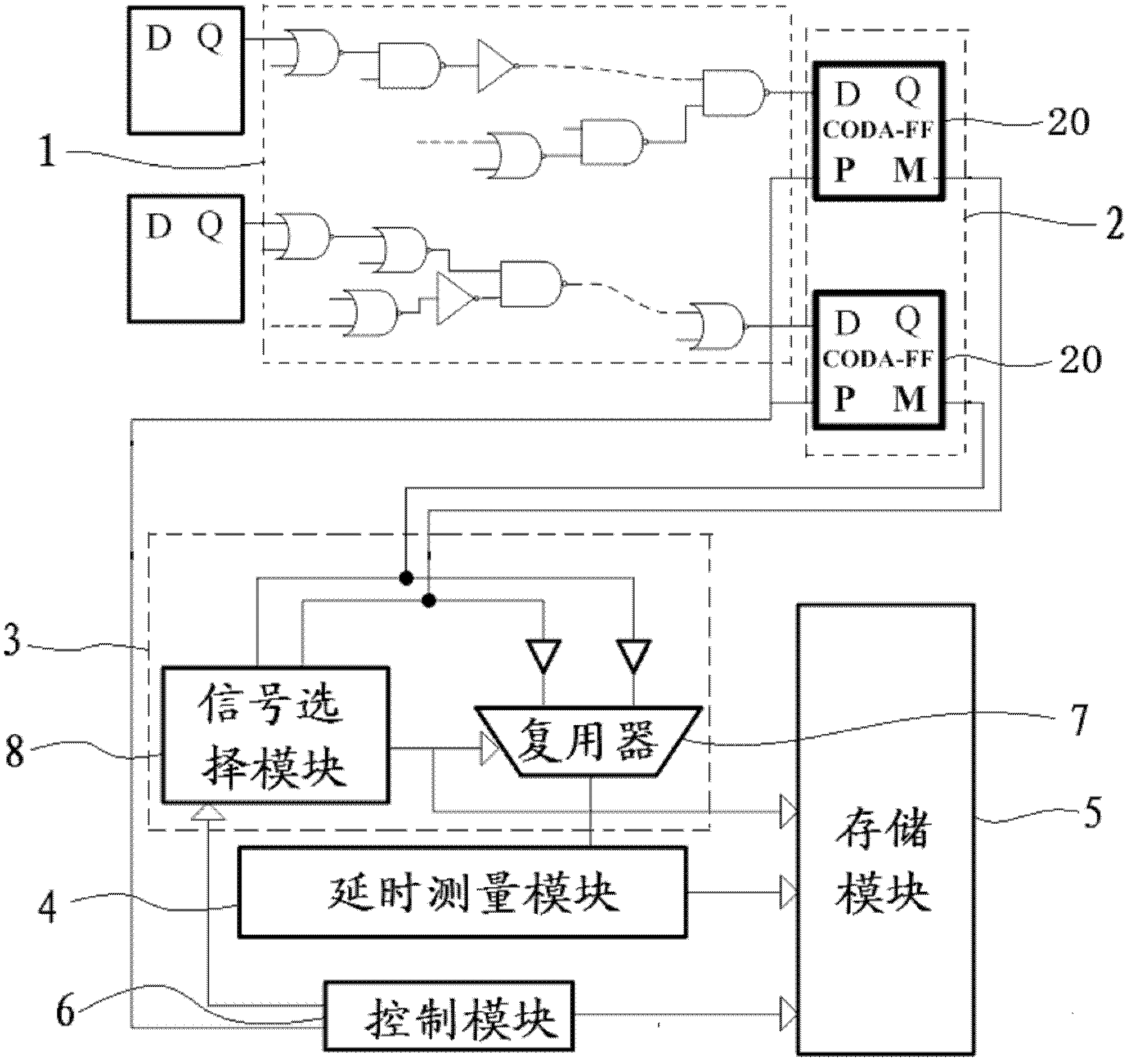
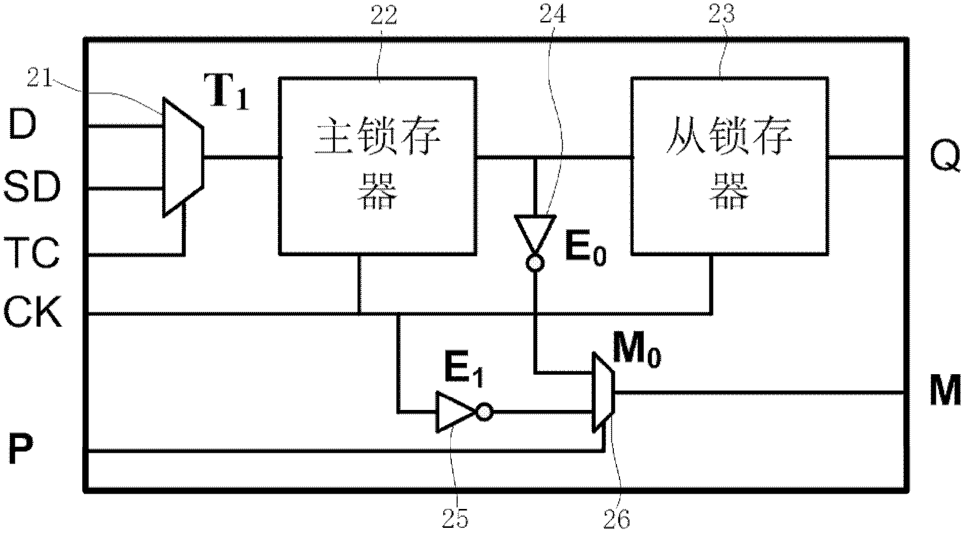
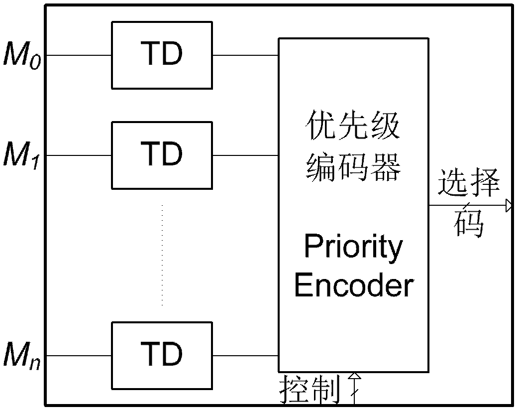
[0026] Please refer to figure 1 , an embodiment of the present invention provides an online path delay measurement circuit. The path delay online measurement circuit includes a measurement trigger module 2 connected to the circuit to be tested 1, a measurement source selection module 3 that is connected to the measurement trigger module 2 and controls the signal from the measurement trigger module 2 to pass through, and a measurement source selection module 3 that is connected to the measurement source The delay measurement module 4 that is connected to the selection module 3 and performs delay measurement on the signal from the source selection ...


PUM


Abstract

A path delay on-line measurement circuit comprises a measurement trigger module connected with a to-be-detected circuit, a to-be-detected source selection module connected with the measurement trigger module and controlling signals sent by the measurement trigger module to selectively pass, a delay measurement module connected with the to-be-detected source selection module and carrying out delay measurement to signals sent by the to-be-detected source selection module, a storage module connected with the delay measurement module and storing delay measurement information of the delay measurement module, and a control module for controlling operation of the measurement trigger module, the to-be-detected source selection module and the storage module. The path delay on-line measurement circuit is connected to the to-be-detected circuit, the control module controls the path delay on-line measurement circuit to work in a probe path delay measurement mode so as to measure and obtain delay of each probe path and controls the path delay on-line measurement circuit to work in an on-line delay measurement mode so as to measure and obtain total delay. Finally, the measured probe path delay is subtracted from the total delay, and the delay of the to-be-detected path is obtained.

Description

【Technical field】 [0001] The invention relates to integrated circuit technology, in particular to a path delay on-line measurement circuit for on-line measurement of path delay on some paths in VLSI. 【Background technique】 [0002] With the continuous improvement of the production process of the semiconductor industry, the continuously upgraded VLSI has shown stronger functions and lower costs. But at the same time, the performance of integrated circuits presents more and more significant unpredictability (that is, their performance varies considerably at different times and environments). This is because factors such as deviations in the production process, changes in environmental parameters during work, and aging effects have more and more serious impacts on the performance of integrated circuits. Correspondingly, for the timing correctness of an integrated circuit (the most important performance index of an integrated circuit in most cases), a common test solution is to...

Claims


Application Information

Patent Timeline
IPC IPC(8): G01R31/28
Inventor 张于彬徐强
Owner SHENZHEN INST OF ADVANCED TECH CHINESE ACAD OF SCI
Learn More