
Control method and control system of interactive electronic whiteboard

An electronic whiteboard and control system technology, applied in the direction of electrical digital data processing, input/output process of data processing, instruments, etc., can solve problems such as waste, complicated equipment systems, cumbersome installation and use, etc., and achieve low cost, simple and convenient equipment The effect of upgrading and improving compatibility

Inactive Publication Date: 2012-06-13
刘文涛
View PDF8 Cites 1 Cited by
  • Summary
  • Abstract
  • Description
  • Claims
  • Application Information

AI Technical Summary

Problems solved by technology

[0005] Disadvantages of the first type of device: ① You must use a signal pen that can automatically light up to write. The signal pen is expensive, not very convenient to use, and easy to damage; very cumbersome
Disadvantages of the second type of device: ①The sensitivity and stability of electronic interaction are low, and the writing clarity is not enough; ②Light-emitting devices and reflective devices need to be arranged around the whiteboard, resulting in complicated equipment systems, messy appearance, and extremely inconvenient installation and use
Due to the poor compatibility of the existing dust-free teaching aid systems, in order to upgrade from non-interactive to interactive, it is often necessary to completely discard the original equipment, resulting in great waste
For example: a unit using an ordinary LCD screen, originally connected the LCD screen directly to the computer for use, which is equivalent to enlarging the computer screen, but without any interactive function. If such a unit wants to upgrade to an interactive operation mode, it needs to be discarded. Expensive LCD screen, repurchase new interactive whiteboard system

Method used


Image

  • Control method and control system of interactive electronic whiteboard
  • Control method and control system of interactive electronic whiteboard

Examples


Embodiment 1

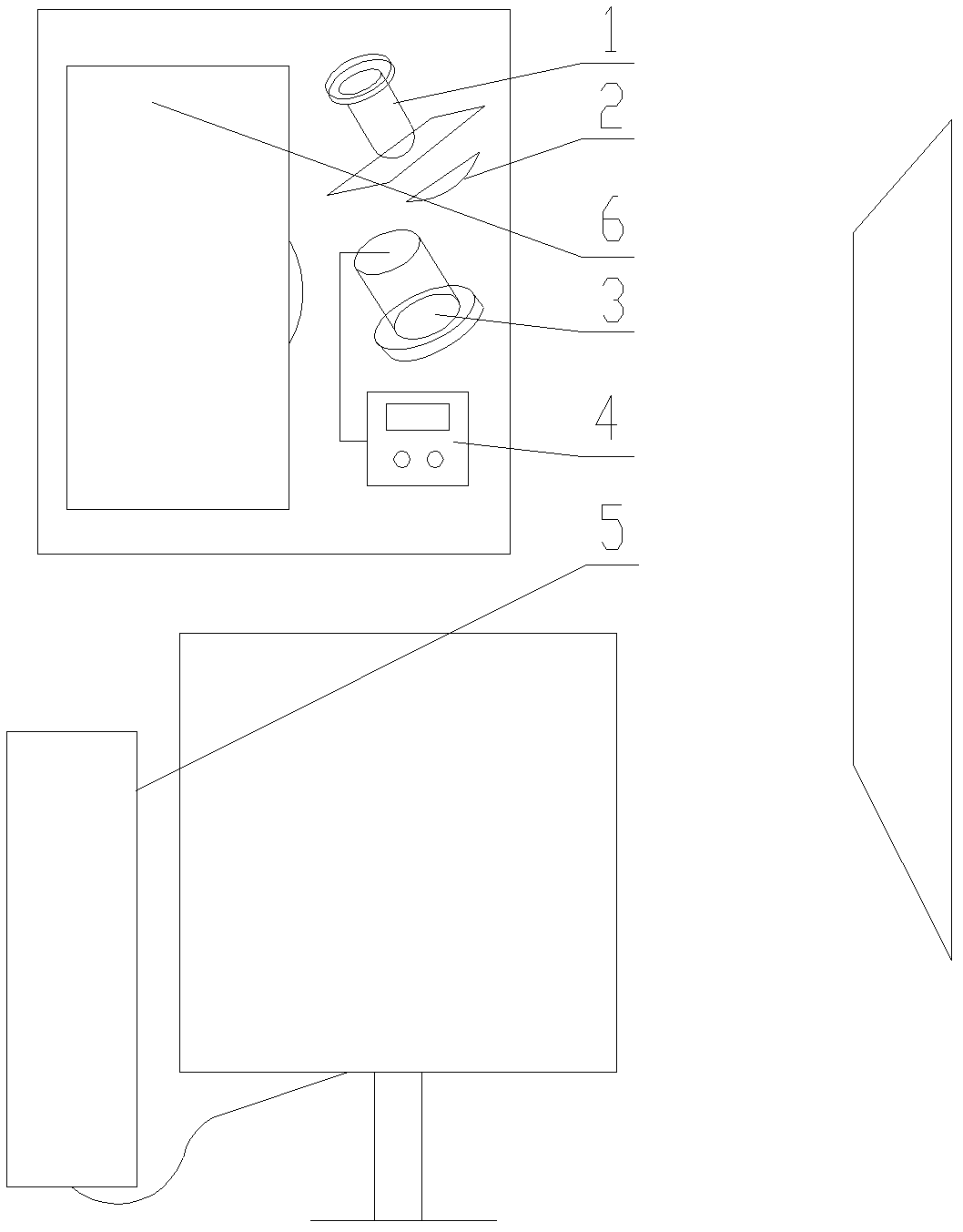
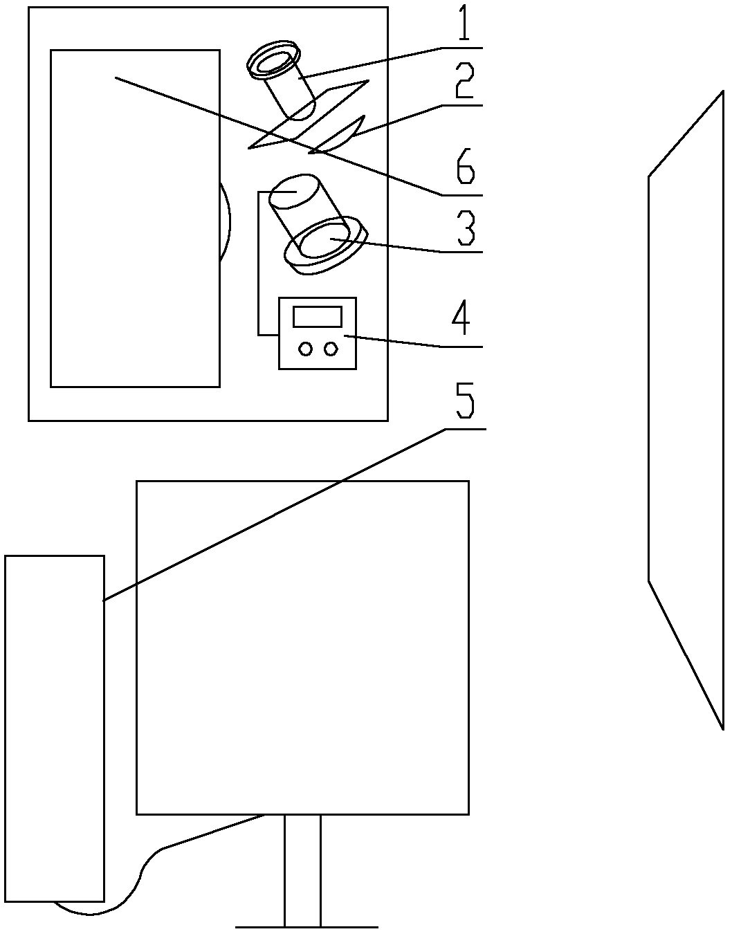
[0033] Referring to the accompanying drawings, the structure of the control system of the interactive electronic whiteboard of the present invention includes a signal generating device 1, a signal receiving device 3, a signal processing device 4, a PC 5, and a display terminal 6. There is also a gap between the signal generating device 1 and the display screen. An optical lens 2 is set, and the signal generating device 1 realizes uniformly projecting a background signal to the display screen through the above-mentioned lens; wherein, the signal generating device 1 is an infrared generator, the signal receiving device 3 is a corresponding induction chip, and the signal processing device 4 is a microcontroller , the display terminal 6 is a projector, and the display screen is a projection screen of the projector;

[0034]In terms of positional relationship, the signal generating device 1, the signal receiving device 3, the signal processing device 4, and the display terminal 6 ar...

Embodiment 2

[0039] The difference between this embodiment and Embodiment 1 is: the display terminal 6 is a liquid crystal display, and the display screen is the display screen of this liquid crystal display; in terms of positional relationship, the signal generating device 1, the signal receiving device 3, the signal processing device The device 4 and the display terminal 6 are set separately; the communication between the signal processing device 4 and the display terminal 6 and the PC 5 is performed through a data line. Other parts of this embodiment and its working principle are consistent with Embodiment 1.


PUM


Abstract

The invention discloses a control method and a control system of an interactive electronic whiteboard. The system structure comprises a signal generation device, a signal receiving device, a signal processing device, a personal computer (PC) and a display terminal. The signal connection relation of the devices is characterized in that the signal generation device evenly projects signals with constant strength to a display screen to enable the signals to serve as background signals, and the signal processing device demarcates receiving quantity of background signals from the signal receiving device as a reference value. When the signal receiving quantity of the signal receiving device is higher than or lower than the reference value, the signal processing device outputs signals, otherwise, the signal receiving device outputs no signals. Output signals of the signal processing device are displayed as writing signals on the PC, and the writing signals on the PC are transmitted to the display terminal for display. The control method and the control system are simple in structure, high in integration degree, strong in stability, simple and convenient to install, debug and use and simultaneously being compatible with two writing modes of 'source' and 'no source'.

Description

technical field [0001] The invention relates to a system control method of an electronic whiteboard, in particular to a system control method of an interactive electronic whiteboard. Background technique [0002] There are two main ways to realize the development of dust-free teaching aids to the stage of electronic whiteboard system: [0003] 1. See Chinese patent: "An Anti-drop Micro-motion Photoelectric Pen", patent number: 201020694292.0. Its structure includes a pen tube and a light-emitting circuit installed in the pen tube. A luminous signal light is set, the rear end of the nib linkage tube is in contact with the micro switch arranged on the light-emitting circuit board through a rebound power-off mechanism, a battery holder is arranged at the rear end of the light-emitting circuit board, and the rear end of the battery holder is the end pen cap; the light-emitting signal light, the micro-switch The switch, the light-emitting circuit board and the power supply are c...

Claims


Application Information

Patent Timeline
Patent Type & Authority Applications(China)
IPC IPC(8): G06F3/042G06F3/043G06F3/046
Inventor 刘文涛
Owner 刘文涛
Learn More