Optical fiber tray

A technology of optical fiber reel and pumping light, which is applied in the field of optical fiber reel, can solve the problems of unfavorable fiber extraction, poor heat dissipation, and inability to maintain, and achieve the effects of convenient long-term stable operation, simple coiling work, compact and practical structure

Active Publication Date: 2012-06-13
HANS LASER TECH IND GRP CO LTD
View PDF7 Cites 4 Cited by
  • Summary
  • Abstract
  • Description
  • Claims
  • Application Information

AI Technical Summary

Problems solved by technology

[0002] In the existing coil heat dissipation technology for fiber laser gain fiber, there are mainly two methods: one is to put the gain fiber and the devices connected with it into a container and adopt the method of integral glue sealing, although this method It can ensure good heat dissipation, but its disadvantages are also obvious, that is, once there is a problem with this part of the device, it will cause inconvenience or even impossible maintenance, and the part can only be discarded as a whole, resulting in unnecessary waste; There are also two ways to coil the gain fiber on the fiber optic disk. One is to use the optical cylinder, and the double-sided adhesive is pasted between the optical fiber and the cylinder, but this method is not only inconvenient to operate, but also the heat dissipation effect is not good; the other method Thread grooves are made on the cylindrical surface of the optical fiber disk, but most of them have deep grooves and are only opened on the cylindrical surface. Part of the gain fiber is suspended or special heat dissipation treatment is required for this section of fiber. In short, the structure is complicated and it is not conducive to the extraction of fibers of different lengths from any position.

Method used


Image

  • Optical fiber tray
  • Optical fiber tray

Examples


Embodiment Construction

[0013] The present invention will be further described below in conjunction with the accompanying drawings and specific embodiments.

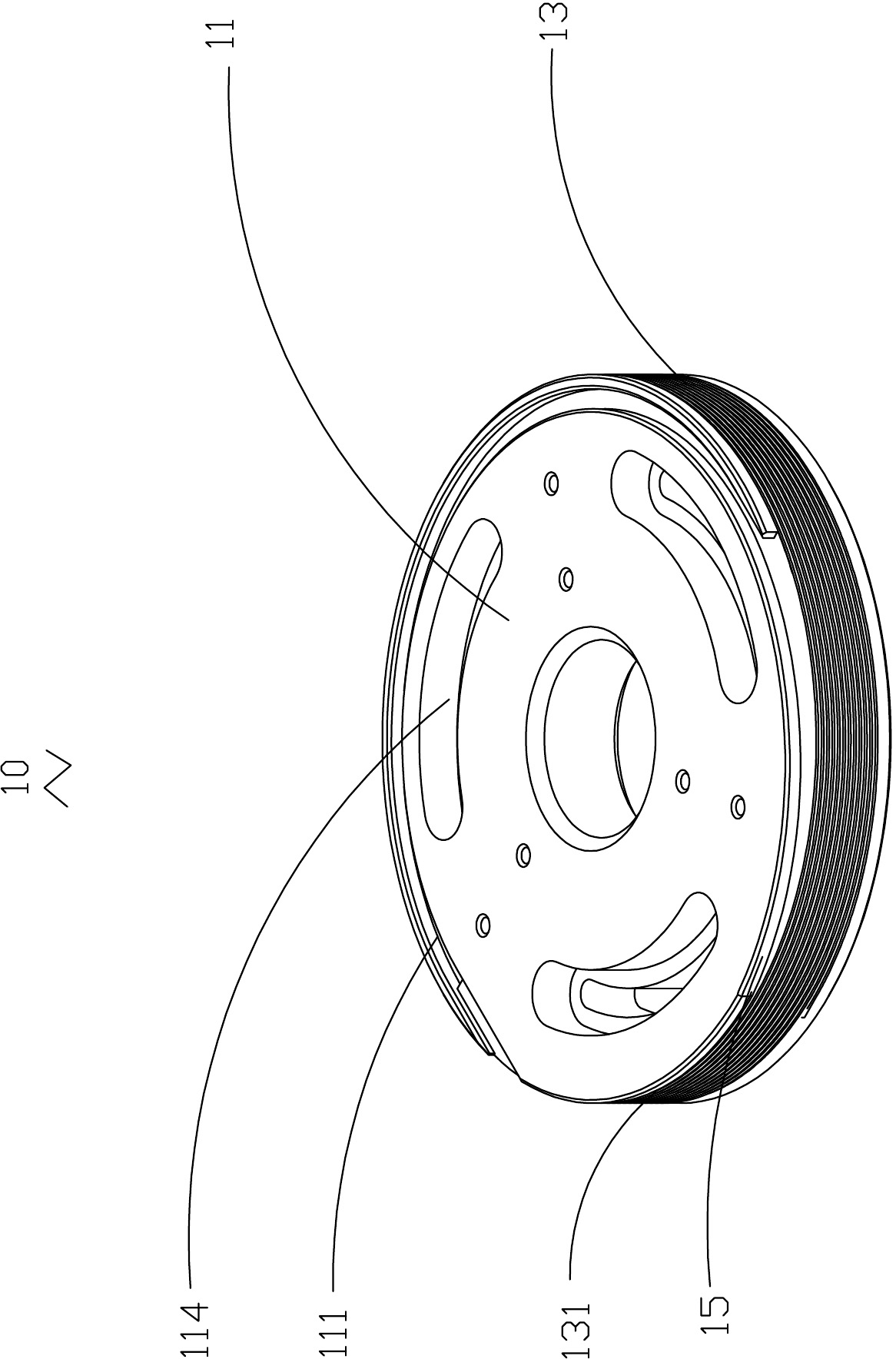
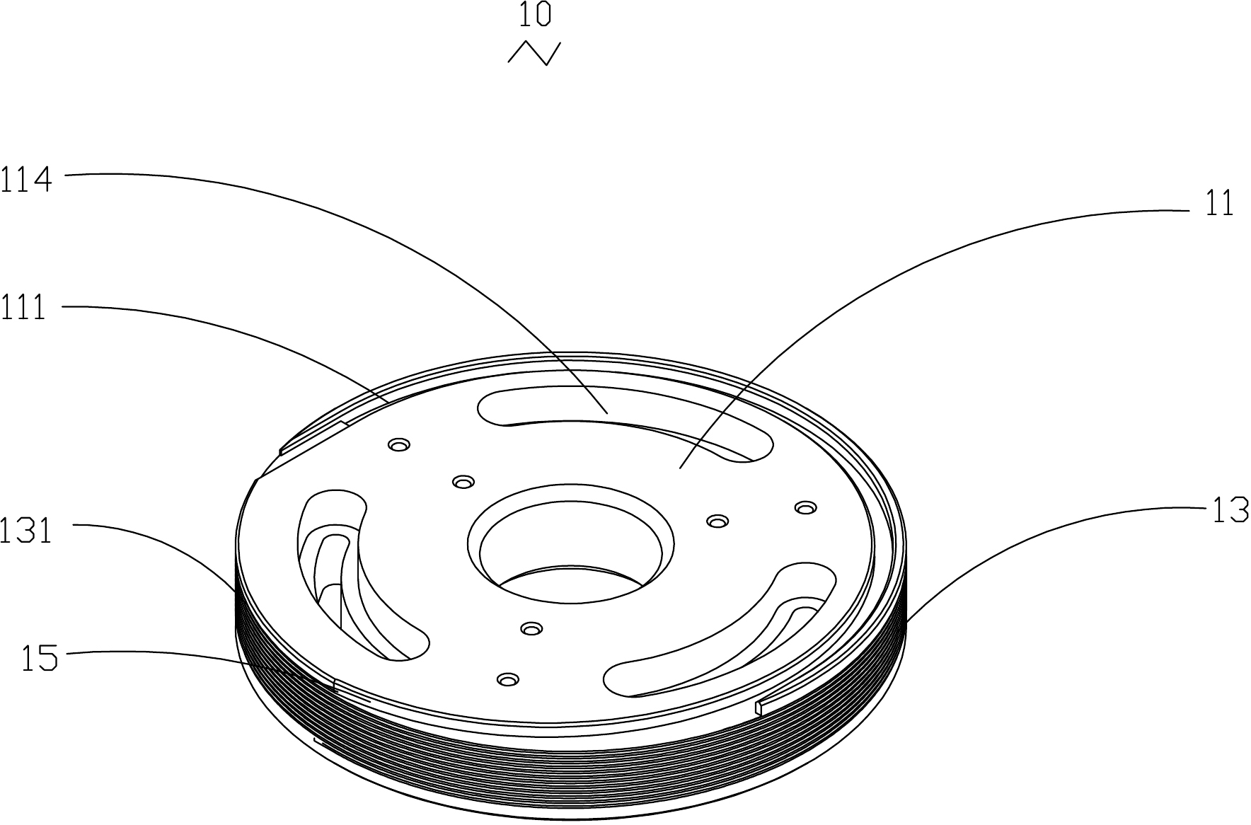
[0014] see figure 1 , the present invention provides an optical fiber reel 10 for coiling optical fibers (not shown). The optical fiber tray 10 includes a top surface 11 and a cylindrical surface 13 connected to the top surface 11, and further includes a separation groove 131 surrounding the cylindrical surface 13, an arc-shaped groove 111 arranged on the edge of the top surface 11, and an arc-shaped groove 111 connected to the top surface 11. The transition groove 15 between the separation groove 131 , the transition groove 15 makes the arc groove 111 and the separation groove 131 smoothly connected.

[0015] In this embodiment, the optical fiber tray 10 is made of aluminum alloy or copper with excellent thermal conductivity.

[0016] In this embodiment, the separation groove 131 is a rectangular threaded groove. It can be understood that t...


PUM


Abstract

The invention provides an optical fiber tray, which is used for coiling optical fibers. The optical fiber tray comprises a top surface and a cylindrical surface, wherein the cylindrical surface is connected to the top surface; separation grooves are formed on the cylindrical surface of the optical tray; and arc grooves are formed on the top surface of the optical fiber tray. Transitional grooves are formed on the optical fiber tray and connected between the arc grooves and the separation grooves to smoothly connect the arc grooves with the separation grooves, and pump light pouring spots are formed in the arc grooves. The optical fiber tray has a practical and compact structure and a good heat radiating effect; and by using the optical fiber tray, the optical fibers are easy to coil, the pigtails of the optical fibers can be drawn out of optional positions in a groove-crossing mode and cannot be damaged, and powerful guarantee can be provided for the convenient integration and the long-term steady operation of lasers.

Description

technical field [0001] The invention relates to an optical fiber disk, in particular to an optical fiber disk integrating optical fiber coil heat dissipation and a pumping light dumping point. Background technique [0002] In the existing coil heat dissipation technology for fiber laser gain fiber, there are mainly two methods: one is to put the gain fiber and the devices connected with it into a container and adopt the method of integral glue sealing, although this method It can ensure good heat dissipation, but its disadvantages are also obvious, that is, once there is a problem with this part of the device, it will cause inconvenience or even impossible maintenance, and the part can only be discarded as a whole, resulting in unnecessary waste; There are also two ways to coil the gain fiber on the fiber optic disk. One is to use the optical cylinder, and the double-sided adhesive is pasted between the optical fiber and the cylinder, but this method is not only inconvenient...

Claims


Application Information

Patent Timeline
Patent Type & Authority Applications(China)
IPC IPC(8): H01S3/067G02B6/44
Inventor 陈建飞吕凤萍马淑贞高云峰
Owner HANS LASER TECH IND GRP CO LTD
Why Eureka
Try Eureka