Pressure compensating drip irrigation emitter with changed structure

A pressure compensation and sprinkler technology, which is applied in watering devices, climate change adaptation, gardening, etc., can solve the problems of low water uniformity, high manufacturing cost, complex structure, etc., and achieve favorable uniformity, low sensitivity, The effect of reducing manufacturing costs

Inactive Publication Date: 2012-06-20
HUAZHONG UNIV OF SCI & TECH
View PDF3 Cites 15 Cited by
  • Summary
  • Abstract
  • Description
  • Claims
  • Application Information

AI Technical Summary

Problems solved by technology

[0005] The purpose of the present invention is to overcome the disadvantages of the existing pressure compensation emitters, such as low uniformity of water output, easy blockage, complex structure, and high manufacturing cost, and to provide a pressure-compensated drip irrigation emitter with a variable structure. The emitter has a simple flow path, It can realize the pressure compensation effect of the emitter, and has good water uniformity and anti-clogging performance

Method used


Image

  • Pressure compensating drip irrigation emitter with changed structure
  • Pressure compensating drip irrigation emitter with changed structure
  • Pressure compensating drip irrigation emitter with changed structure

Examples


Embodiment Construction

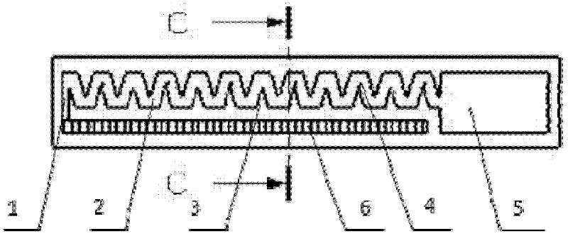
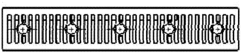
[0013] The emitter is an inlaid drip irrigation belt, and the flow channel structure is a zigzag labyrinth. Wherein, the sawtooth structure is linear and evenly distributed, and the elastic retaining pieces are spaced and equidistantly distributed on the sawtooth structure. The width of the elastic flap is slightly smaller than the thickness of the sawtooth, and its inclination direction is consistent with the direction of water flow. The elastic flap will bend and swing to varying degrees under different water pressures, so that the flow cross-sectional area in the flow channel changes with the pressure. And change, to achieve the pressure compensation effect. Below in conjunction with accompanying drawing and example the concrete working mode of the present invention is described in further detail:

[0014] The present invention requires the emitter to obtain a stable water outlet flow within a certain working water head (pressure) range. Such as Figure 1.1 As shown, the ...


PUM


Abstract

The invention discloses a pressure compensating drip irrigation emitter with a changed structure. The structure of the pressure compensating drip irrigation emitter is that a water inlet is communicated with one end of a flow path, a water outlet is communicated with the other end of the flow path, linear sawtooth ends are evenly distributed on two sides in the flow path, and elastic blocking pieces are distributed at the sawtooth ends at equidistant intervals. The width of elastic blocking pieces is slightly smaller than the thickness of sawteeth so that friction between the elastic blocking pieces and the flow path is avoided. The deflection direction of the elastic blocking pieces is the direction of water flow. A back fence is arranged at the back of the irrigation emitter and is communicated with the water inlet. By adding the elastic blocking pieces on tooth-shaped structure ends of a traditional labyrinth flow path, the irrigation emitter achieves the purpose of integral design of compensating pieces and the flow path so that assembly errors between the compensating pieces and the flow path are reduced, and local head loss caused by the assembly is reduced. The novel flow path can achieve pressure compensation, can be used in production of embedded-in drip irrigation belts, and can solve the problem that the drip irrigation belts are not suitable for achieving the pressure compensation. Besides, the pressure compensating drip irrigation emitter further has capacities of self cleaning and blocking resistance.

Description

technical field [0001] The invention belongs to the intersection field of agricultural water-saving irrigation and advanced manufacturing technology, and in particular relates to a variable-structure pressure-compensated drip irrigation dispenser. Background technique [0002] Water-saving irrigation is the main measure adopted by countries in the world to develop agriculture. As an advanced high-standard irrigation technology in water-saving irrigation, micro-irrigation has been adopted by many countries in the world. Among them, drip irrigation has the most obvious advantages such as water saving, production increase, and high efficiency, and can be widely used in the cultivation of economic crops such as fruit trees, vegetables, flowers, and medicinal materials. The emitter is the core component of the drip irrigation system, and its performance plays a decisive role in the promotion and application of the entire drip irrigation system. [0003] The pressure-compensated ...

Claims


Application Information

Patent Timeline
Patent Type & Authority Applications(China)
IPC IPC(8): A01G25/02
CPCY02A40/22
Inventor 刘洁魏青松陆恒殷莉黎安王聪芦刚史玉升
Owner HUAZHONG UNIV OF SCI & TECH
Why Eureka
Try Eureka