Sleeve mounting mechanism

A sleeve and collecting frame technology, applied in the field of upper sleeve mechanism, can solve the problems of no sleeve centering device, low quality of upper sleeve, high labor intensity, etc., achieve simple structure, easy maintenance and repair, reduce The effect of labor intensity

Inactive Publication Date: 2012-06-20
CHINA NAT HEAVY MACHINERY RES INSTCO
View PDF8 Cites 11 Cited by
  • Summary
  • Abstract
  • Description
  • Claims
  • Application Information

AI Technical Summary

Problems solved by technology

This leads to the problem of loading the sleeve. The existing sleeve loading methods are as follows: 1. Manual sleeve loading (limited paper sleeve), 2. Crane and roll unloading trolley cooperate with the sleeve loading, 3. Using the sleeve On the sleeve device, but the structure is complicated and there is no sleeve centering device
The above methods have many shortcomings such as high labor intensity, unsafe, low efficiency and low quality of the upper sleeve.

Method used


Image

  • Sleeve mounting mechanism
  • Sleeve mounting mechanism
  • Sleeve mounting mechanism

Examples


Embodiment

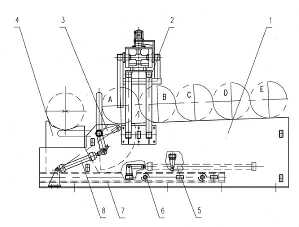
[0021] Such as figure 1 As shown, it is mainly composed of a sleeve collecting frame 1, a sleeve centering device 2, a fan-shaped shift fork 3, and a movable frame 4. Four major parts are formed. Socket collection rack 1 is welded by steel plate and used to store sleeves. The upper surface of sleeve collection rack 1 is an inclined plane, that is, the working surface for storing sleeves is an inclined plane; the inclination is the best inclination of 2°-3° It is 2.5 degrees.

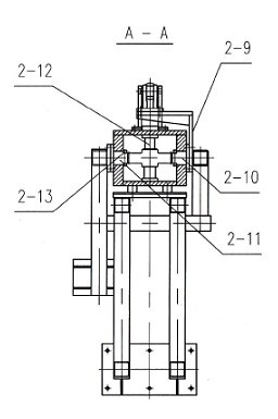
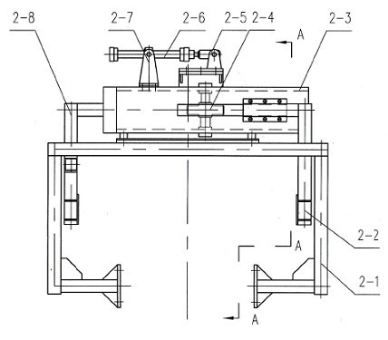
[0022] In addition, sleeve collecting frame 1 is processed with installation sleeve centering device 2, shift fork 3, movable frame 4, movable frame drive oil cylinder 5 and the installation position of shift fork drive oil cylinder 8. The sleeve centering device 2 is fixedly installed on the sleeve collecting rack 1 with bolts. Sector shift fork 3 is installed on the sleeve collecting frame 1 by slide bearing 3-3 and slide bearing 3-7. Movable frame 4 is installed on the inboard of sleeve collecting ...


PUM


Abstract

The invention relates to a sleeve mounting mechanism used during the production process of plates. The sleeve mounting mechanism is characterized by mainly comprising a sleeve collection rack, a sleeve centring device, a shift fork and a moving frame; the sleeve centring device, the shift fork and the moving frame are connected to the sleeve collection rack; the moving frame is in transmission connection with a moving frame driving oil cylinder; the shift fork is in transmission connection with a shift fork driving oil cylinder; the sleeve centring device is fixed on the sleeve collection rack; and the shift fork is connected to the sleeve collection rack through a slide bearing I and a slide bearing II. The sleeve mounting mechanism has complete functions, integrates the functions of sleeve centring and sleeve mounting, can realize automation in sleeve mounting, is provided with the sleeve centring device to ensure that a sleeve is mounted correctly on a winding drum, has high degree of mechanization, accomplishes all the operations of centring, conveying and transportation of sleeves without manual assistance, and is simple in structure and easy in maintenance and overhaul.

Description

technical field [0001] The invention relates to an upper sleeve mechanism in the plate production process. Background technique [0002] In the plate production process, in order to improve product quality and yield, sleeves are often used. This leads to the problem of loading the sleeve. The existing sleeve loading methods are as follows: 1. Manual sleeve loading (limited paper sleeve), 2. Crane and roll unloading trolley cooperate with the sleeve loading, 3. Using the sleeve On the sleeve device, but the structure is complicated and there is no sleeve centering device. There are many shortcomings such as high labor intensity of workers in the above method, unsafe, low efficiency and low quality of the upper sleeve. Contents of the invention [0003] The present invention aims to solve the above technical problems and provide a fully functional upper sleeve mechanism to overcome the defects in the prior art. [0004] The technical solution of the present invention is ...

Claims


Application Information

Patent Timeline
Patent Type & Authority Applications(China)
IPC IPC(8): B21C47/24
Inventor 姚养库王鹏张康武刘忠宝
Owner CHINA NAT HEAVY MACHINERY RES INSTCO
Why Eureka
Try Eureka