Parallelogram type connection table

A parallelogram, connecting table technology, which is applied to conveyor objects, transportation and packaging, etc., can solve the problems of large space occupation, difficulty in adjusting the width of the feeding board, low transportation efficiency, etc., and achieves low manufacturing cost, low working noise, The effect of fast board transport

Inactive Publication Date: 2012-06-20
DONGGUAN SCIENCGO MACHINERY MFG
View PDF5 Cites 30 Cited by
  • Summary
  • Abstract
  • Description
  • Claims
  • Application Information

AI Technical Summary

Problems solved by technology

[0002] The connection table is a kind of transportation equipment for the intermediate transition of PCB circuit boards from one processing equipment to another processing equipment. Since the horizontal positions and heights of the two processing equipment are different, the connection table The functions mainly include horizontal transportation and vertical transportation. The connecting table generally realizes the horizontal transportation function of the PCB circuit board through the board feeding device, and realizes the vertical transportation function of the PCB circuit board by moving the lifting plate up and down. The horizontal transportation and the vertical transportation are determined by Realized by different driving mechanisms, the structure of the existing docking station is relatively complex, it takes up a lot of space, it is difficult to assemble, the transportation efficiency is low, the noise is loud during work, and the environment is seriously polluted
[0003] In addition, the existing plate feeding device is difficult to adjust the width of the plate feeding, especially the driving part of the plate feeding needs to be adjusted and modified accordingly. The adjustment process is complicated, which greatly affects the production efficiency of the connecting table, and the defects are obvious

Method used


Image

  • Parallelogram type connection table
  • Parallelogram type connection table
  • Parallelogram type connection table

Examples


Embodiment Construction

[0019] In order to facilitate the understanding of those skilled in the art, the present invention will be further described below in conjunction with the embodiments and accompanying drawings, and the contents mentioned in the embodiments are not intended to limit the present invention.

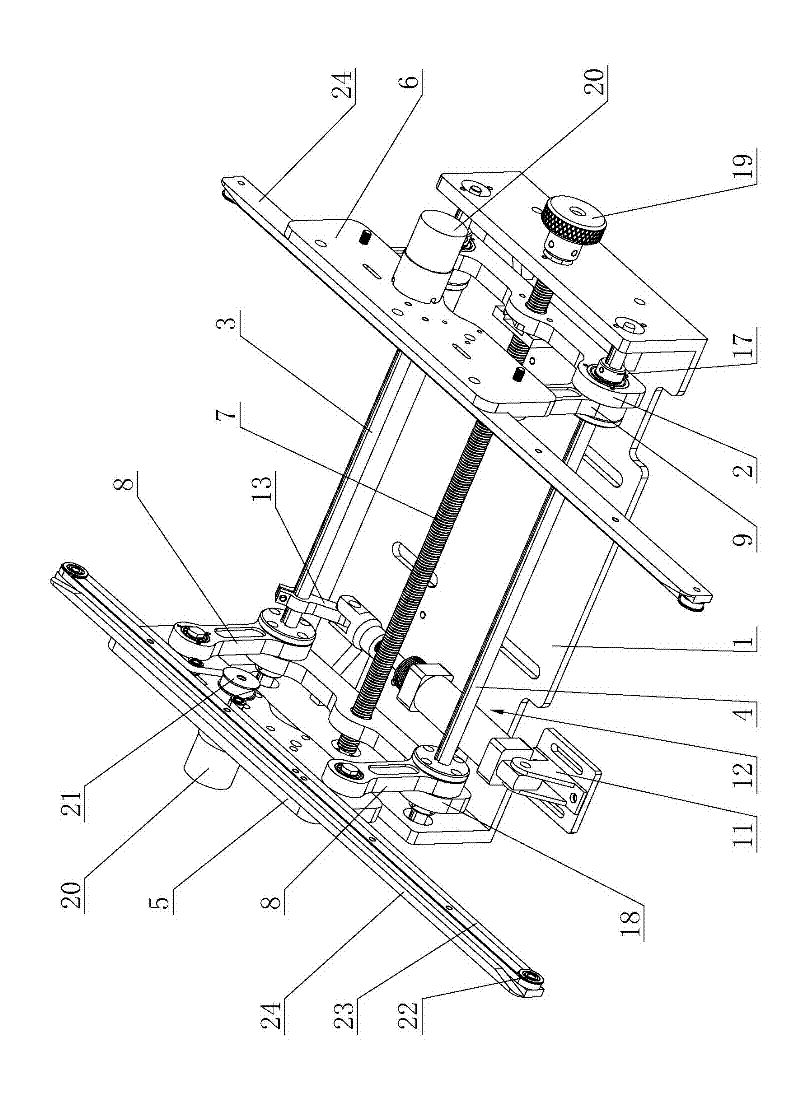
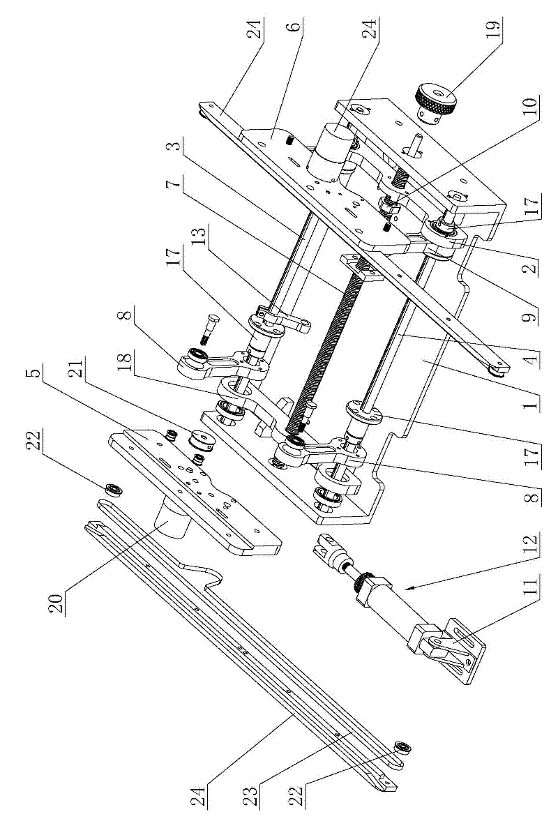
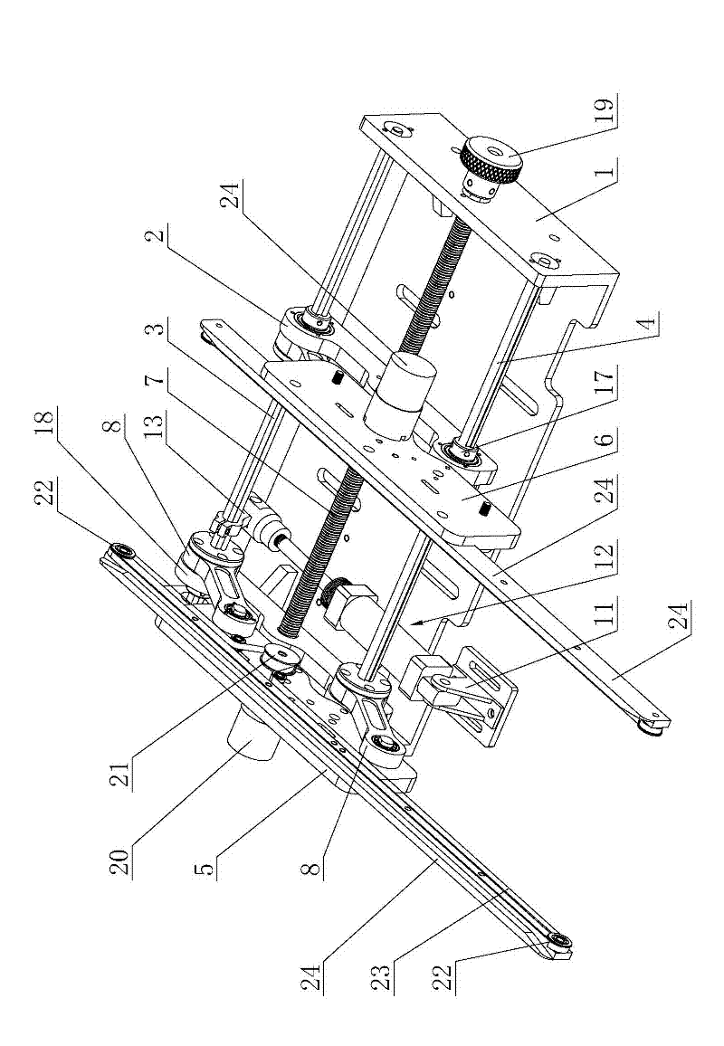
[0020] Such as Figure 1 to Figure 4 Shown is the first embodiment of the parallelogram form connecting platform of the present invention, including the base 1, the movable connecting block 2, the rotating main rod 3 and the balance rod 4 arranged in parallel with the rotating main rod 3, and the two sides of the rotating main rod 3 Both ends of the end and the balance bar 4 are connected to the base 1, and the two ends of the movable connection block 2 are respectively sleeved on the rotating main bar 3 and the balance bar 4, and also include a fixed support plate 5, a movable support plate 6, and an adjustment screw 7 , two transporting devices and a driving mechanism for driving the rotat...


PUM


Abstract

The invention relates to the technical field of delivery equipment of printed circuit boards (PCBs), in particular to a parallelogram type connection table, which comprises a base, a movable connection block, a rotary main rod, a balancing rod parallel to the rotary main rod, a fixing support board, a movable support board, an adjusting lead screw, two board conveying devices and a driving mechanism for driving the rotary main rod to rotate. The parallelogram type connection table can achieve the aim of adjusting the width of delivered boards by rotating the lead screw and is convenient to adjust, the rotary main rod is driven to rotate under the effect of the driving mechanism and drives a movable rotary arm and a fixed rotary arm to swing, so that the movable support board and the fixed support board translate leftwards or downwards simultaneously, or the movable support board and the fixed support translate rightwards and upwards. Accordingly, transverse conveying and longitudinal conveying functions of the parallelogram type connection table are achieved, and the parallelogram type connection table is small and exquisite in structure, light in weight, convenient to assemble, low in manufacture cost, small in working noise, fast in board conveying speed and high in board delivery efficiency.

Description

technical field [0001] The invention relates to the technical field of PCB circuit board conveying equipment, in particular to a parallelogram form connecting platform. Background technique [0002] The connection table is a kind of transportation equipment for the intermediate transition of PCB circuit boards from one processing equipment to another processing equipment. Since the horizontal positions and heights of the two processing equipment are different, the connection table The functions mainly include horizontal transportation and vertical transportation. The connecting platform generally realizes the horizontal transportation function of the PCB circuit board through the board feeding device, and realizes the vertical transportation function of the PCB circuit board by moving the lifting plate up and down. The horizontal transportation and the vertical transportation are determined by Realized by different driving mechanisms, the structure of the existing docking st...

Claims


Application Information

Patent Timeline
Patent Type & Authority Applications(China)
IPC IPC(8): B65G47/74B65G47/52
Inventor 钟显辉苏凯波黎旺曾翔清陈卓标
Owner DONGGUAN SCIENCGO MACHINERY MFG
Why Eureka
Try Eureka