Impeller of centrifugal fan and centrifugal fan

A centrifugal fan and impeller technology, which is applied in the direction of machines/engines, mechanical equipment, liquid fuel engines, etc., can solve the problems of low aerodynamic efficiency and high energy consumption, so as to reduce operating energy consumption, increase effective power, and reduce flow channels Effect of Blocking Coefficient

Active Publication Date: 2012-06-20
ZOOMLION ENVIRONMENTAL IND CO LTD
View PDF4 Cites 12 Cited by
  • Summary
  • Abstract
  • Description
  • Claims
  • Application Information

AI Technical Summary

Problems solved by technology

[0004] The embodiment of the present invention provides a centrifugal fan impeller and a centrifugal fan, which are used to solve th

Method used


Image

  • Impeller of centrifugal fan and centrifugal fan
  • Impeller of centrifugal fan and centrifugal fan
  • Impeller of centrifugal fan and centrifugal fan

Examples


Embodiment Construction

[0027] The specific implementation manners of the centrifugal fan impeller and the centrifugal fan provided by the embodiments of the present invention will be described below with reference to the drawings in the description.

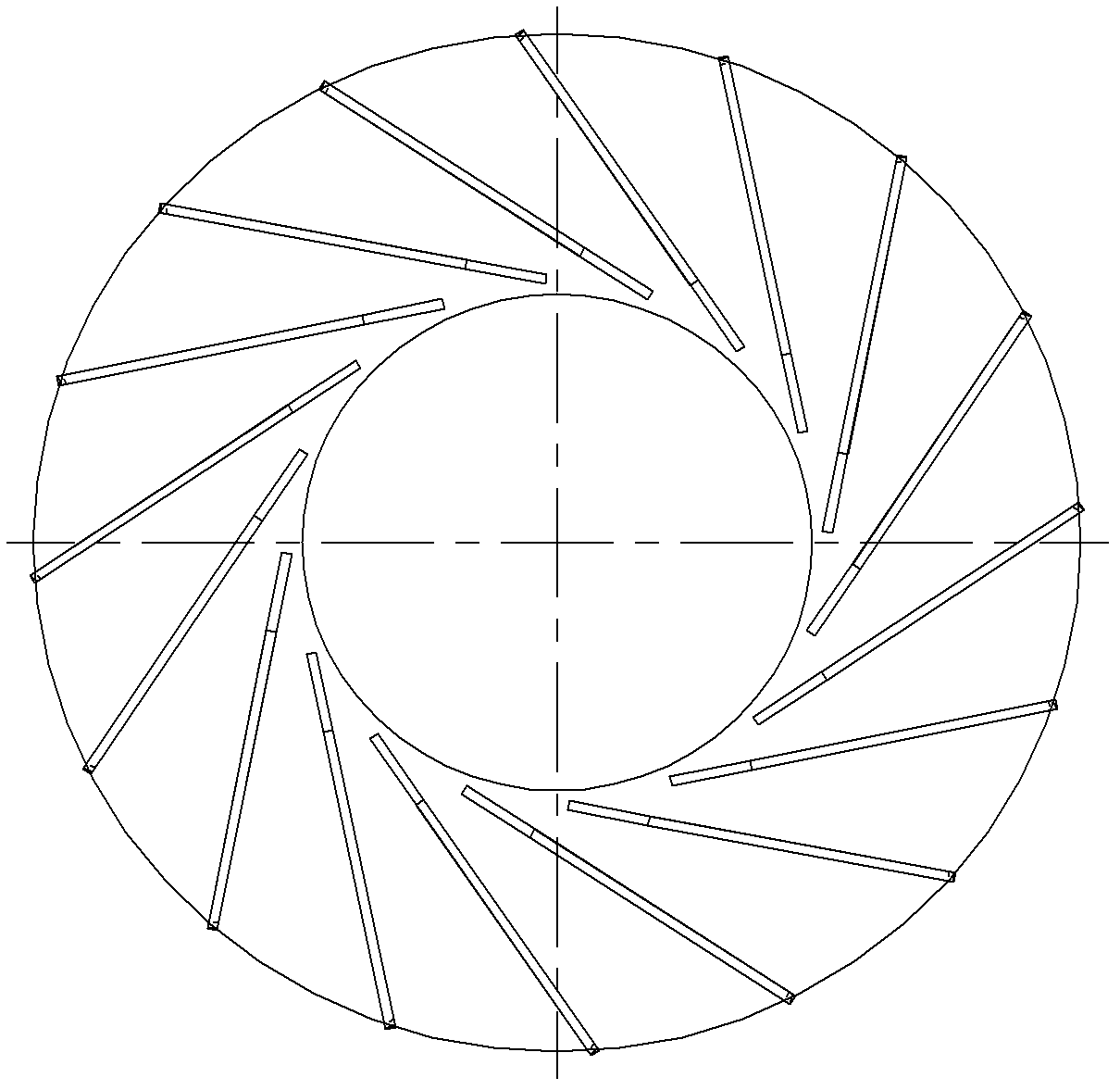
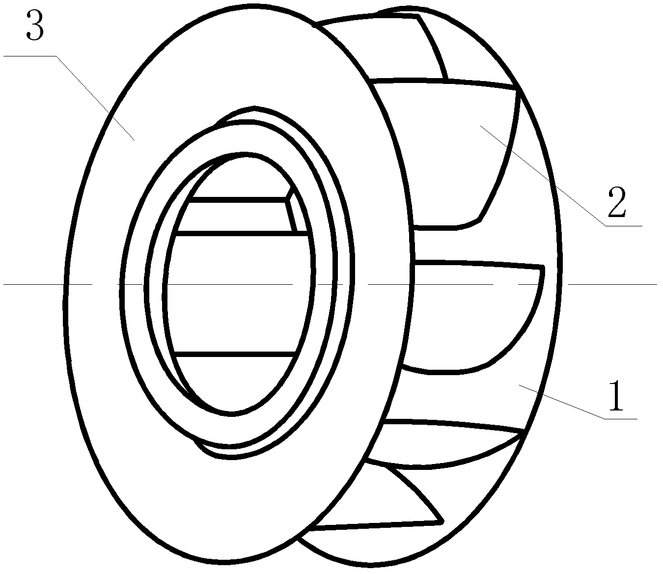
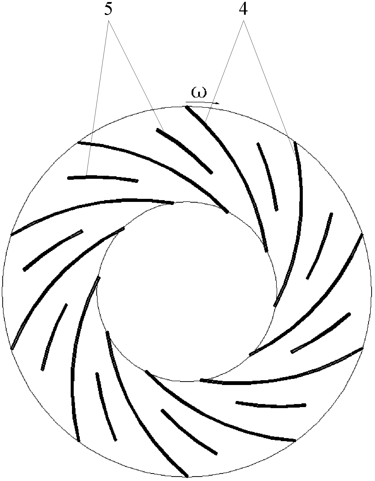
[0028] The centrifugal fan impeller provided by the embodiment of the present invention, such as figure 2 Shown is similar to the prior art, including: hub 1, blade 2 and wheel cover 3 parts, blade 2 is installed between hub 1 and wheel cover 3, the difference is that the embodiment of the invention is for the existing centrifugal fan impeller The blades have been improved, image 3 Shown is a schematic diagram of the overall structure of the blade of the centrifugal fan impeller provided by the embodiment of the present invention, from image 3 It can be seen that the impeller of the centrifugal fan provided by the embodiment of the present invention provides two types of blades, namely the backward long blade 4 and the backward short blade 5, where...


PUM


Abstract

The invention provides an impeller of a centrifugal fan and the centrifugal fan containing the impeller of the centrifugal fan. The impeller of the centrifugal fan comprises a wheel hub, vanes and a wheel cap, wherein the vanes are installed between the wheel hub and the wheel cap, the vanes comprise a backward long vane and a backward short vane, and the length of the flow direction of the long vane is greater than the length of the flow direction of the short vane; and moreover, the long vane and the short vane are in alternate distribution between the wheel hub and the wheel cap, and the inlet diameter of the short vane is greater than the inlet diameter of the long vane. According to the impeller of the centrifugal fan and the centrifugal fan containing the impeller of the centrifugal fan, the problems of lower pneumatic efficiency and larger energy consumption which are brought by the structure of a traditional centrifugal impeller can be solved.

Description

technical field [0001] The invention relates to the field of engineering machinery, in particular to a centrifugal fan impeller and a centrifugal fan. Background technique [0002] The centrifugal fan is a machine that relies on the input mechanical energy to increase the gas pressure and discharge the gas. It is a driven fluid machine. The impeller is an important part of the centrifugal fan. The working principle of the centrifugal fan is that the gas passes through the centrifugal force through its impeller. The center sucks in, then flows between the blades and out. [0003] The impeller is usually composed of hub, blade and wheel cover. Taking the road sweeper as an example, the blades of the impeller of the centrifugal fan used are mostly of the backward straight blade type with 16 blades, such as figure 1 As shown, this kind of blade structure is difficult to adapt to the flow characteristics of the gas inside the fan, and it is easy to form the rigid impact of the a...

Claims


Application Information

Patent Timeline
IPC IPC(8): F04D29/28F04D29/30
Inventor 张斌彭林斌张劲刘之安肖庆麟罗邵均杨志彭宴波
Owner ZOOMLION ENVIRONMENTAL IND CO LTD
Why Eureka
Try Eureka