Pipe placing device for ground source heat pump buried pipe

A technology of ground source heat pumps and buried pipes, which is applied in the direction of pipes/pipe joints/fittings, pipe laying and maintenance, mechanical equipment, etc., and can solve problems such as increasing costs, reducing heat exchange effects, and easily damaged pipes

Inactive Publication Date: 2012-06-20
湖南凌天科技有限公司
View PDF8 Cites 5 Cited by
  • Summary
  • Abstract
  • Description
  • Claims
  • Application Information

AI Technical Summary

Problems solved by technology

[0003] At present, the underground pipes used in ground source heat pump air conditioners are deep in the well during the construction process, and the mud water in the well has a large buoyancy on the pipes. The density of the heat exchange pipes and U-shaped bends made of PE materials is much lower than that of mud water. Density, so the tube cannot be lowered by gravity. The current common practice is to install a long bolt in the middle of the U-shaped bend. The construction personnel use the metal rod to send the heat exchange tube and the U-shaped bend to the predetermined depth through the long bolt. The construction of metal rods is easy to damage the pipe, and the construction is difficult. Before the backfill after the pipe is completed, if the PE heat exchange pipe is not fixed well, it is easy to float up under the action of buoyancy and reduce the heat exchange effect. Therefore, generally after the pipe is completed, it must be Timely backfilling, resulting in generally sloppy leak detection work after the pipe is installed. In case of accidents such as damage to the heat exchange tube during the pipe installation process, the entire geothermal well can only be scrapped, causing great losses
[0004] The "A U-shaped Elbow for Ground Source Heat Pump" provided by patent 201020121183.X solves this problem well. However, because the counterweight is below the device, it occupies part of the depth of the ground source well, requiring more drilling and increasing the Especially in the rock formation area, the drilling cost of a ground source well occupied by a counterweight device is equivalent to the cost of dozens or even hundreds of U-shaped bends, thus increasing the cost and limiting the use to a certain extent

Method used


Image

  • Pipe placing device for ground source heat pump buried pipe
  • Pipe placing device for ground source heat pump buried pipe
  • Pipe placing device for ground source heat pump buried pipe

Examples


specific Embodiment approach

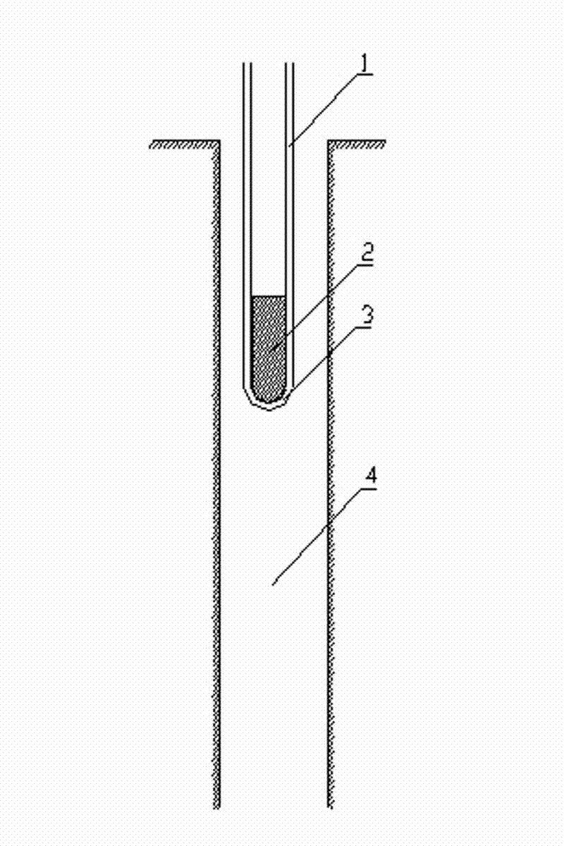
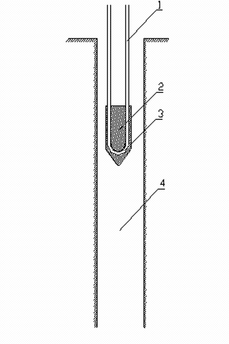
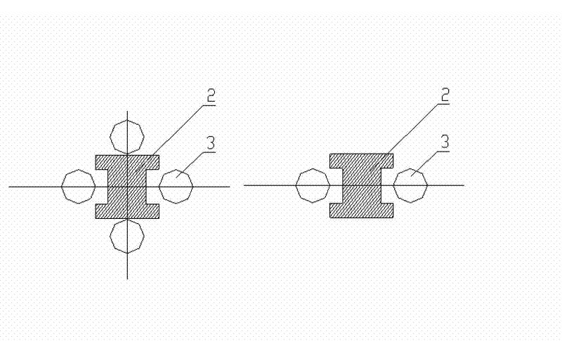
[0022] Specific embodiments: The following is a further description of the ground-source heat pump underground pipe down-pipe device of the present invention in conjunction with the accompanying drawings.

[0023] 1. If figure 1 , the lower end and the outer side do not protrude from the bottom of the U-shaped bend and the outer ground-source heat pump underground pipe lowering device. When the pipe is lowered, place the prefabricated ground-source heat pump underground pipe lowering device on the U-shaped bend At the top, it is temporarily fixed in the middle of 2 or 4 buried PE heat exchange tubes. Due to the heavy weight of the ground source heat pump underground pipe down pipe device, it can overcome the buoyancy of the PE heat exchange tubes and U-shaped bends. Therefore, under the action of its own gravity, it can smoothly reach the bottom of the ground source well and complete the pipe running process. The main advantage of this embodiment is that the ground source he...


PUM


Abstract

The invention provides a pipe placing device for a ground source heat pump buried pipe. The device is prepared from concrete or cement mortar or other materials and is of a long bar shape. During the pipe placing operation, the device is clamped between heat exchange pipelines at the upper part of a U-shaped bend and completes the pipe placing operation by virtue of self weight. The cross section of the device is designed into different shapes. The device provided by the invention has the advantages of being convenient in construction, saving time, saving labor, lowering drilling cost, reducing construction cost, being convenient for hitting operation after pipe placing.

Description

technical field [0001] The invention belongs to the field of ground source heat pumps, in particular to a tube lowering device for buried tubes of ground source heat pumps. Background technique [0002] Ground source heat pump air conditioners use a large amount of low-temperature heat energy stored in underground soil, rocks, groundwater or other media to provide heating, air conditioning and hot water for building spaces. In summer, the waste heat removed by the air conditioner is transported underground, and in winter, the heat in the soil is extracted to provide heating for the air conditioner. Ground source heat pump is by far the most comfortable, efficient, environmentally friendly and energy-saving technology. It is the latest and highest-grade air-conditioning and heating system in the world and has been widely used. [0003] At present, the underground pipes used in ground source heat pump air conditioners are deep in the well during the construction process, and ...

Claims


Application Information

Patent Timeline
Patent Type & Authority Applications(China)
IPC IPC(8): F16L1/028
Inventor 李明
Owner 湖南凌天科技有限公司
Why Eureka
Try Eureka