Infrared heating plate made of carbon fiber composite materials

A composite material and carbon fiber technology, which is applied in the direction of gas fuel burners, lighting and heating equipment, combustion methods, etc., can solve problems in the field of gas infrared burners, and achieve the effect of ensuring production quality and reducing impact

Inactive Publication Date: 2012-06-20
苏婉玲
View PDF9 Cites 2 Cited by
  • Summary
  • Abstract
  • Description
  • Claims
  • Application Information

AI Technical Summary

Problems solved by technology

[0009] The new material formed by compounding carbon fiber and ceramic material is used in the aerospace field and also in the automotive field. Its application range is being gradually expanded by people. At present, it has not been used in the field of gas infrared burners.

Method used


Image

  • Infrared heating plate made of carbon fiber composite materials
  • Infrared heating plate made of carbon fiber composite materials
  • Infrared heating plate made of carbon fiber composite materials

Examples


Embodiment 1

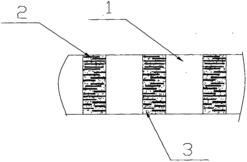
[0024] Such as figure 1 As shown, the carbon fiber composite infrared heating plate is composed of a honeycomb structure, the honeycomb holes 1 are round or square holes and arranged in an orderly manner, and the shape is round or rectangular; the honeycomb structure of the carbon fiber composite infrared heating plate It is composed of base material, aggregate and auxiliary materials, the base material is ceramic material, the aggregate 2 is carbon fiber filaments with a length of 1-6 mm, and the auxiliary materials include at least bonding materials and lubricating materials , the carbon fiber filaments are dispersed in the mixture body 3 formed after the base material and auxiliary materials are mixed.

Embodiment 2

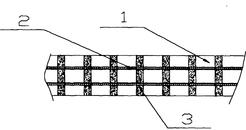
[0026] Such as figure 1 As shown, the carbon fiber composite material infrared heating plate is composed of a honeycomb structure. The honeycomb holes 1 are round holes or square holes and are arranged in an orderly manner. Composite auxiliary materials, the base material is ceramic material, the aggregate 2 is a carbon fiber mesh with a mesh size greater than 0.5 mm, the auxiliary materials include at least bonding materials and lubricating materials, and the carbon fiber mesh is double-layered The shape is placed in the mixed material body 3 formed after the base material and the auxiliary material are mixed, and is surrounded by the mixed material body 3 .

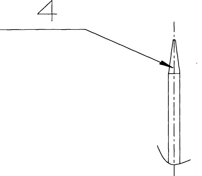
[0027] In the above embodiments, the carbon fiber composite material infrared heating plate is formed by molding or extrusion, and on the forming die, the top 4 of the steel needle used to form the honeycomb hole is in the shape of a cone.

[0028] In the above embodiments, far-infrared materials or combustion catalyst...


PUM

PropertyMeasurementUnit
Mesh sizeaaaaaaaaaa
Cross-sectional areaaaaaaaaaaa
Hole wall thicknessaaaaaaaaaa

Abstract

The invention discloses an infrared heating plate made of carbon fiber composite materials, and is used for a gas infrared burner. The infrared heating plate is formed by a honeycomb structure body, wherein the honeycomb structure body is formed by compositing a base material, aggregates and auxiliary materials; the base material at least comprises a ceramic material or non-metal refractory material; the aggregates are carbon fiber materials which at least comprise carbon fiber filaments, carbon fiber meshes, carbon fiber fabrics and carbon fiber particles; the auxiliary materials at least comprise a bonding material and a lubricating material; and the carbon fiber materials 2 are dispersed in a mixed material body 3 or enclosed by the mixed material body 3. According to the infrared heating plate, the strength is far higher than that of a ceramic honeycomb body heating plate, and the burning performance and the economy are obviously superior to those of a metal honeycomb body heating plate. By utilization of the infrared heating plate disclosed by the invention, the infrared heating plate of two major carbon fiber composite materials, namely ceramic-based and non-metal-refractory-material-based materials can be formed and can be widely used for an infrared gas appliance and infrared gas equipment.

Description

technical field [0001] The invention relates to a heating plate used in an infrared gas appliance and a combustion device of the infrared gas equipment, in particular to a carbon fiber composite material infrared heating plate with a honeycomb structure. Background technique [0002] At present, on the combustion devices of infrared gas appliances and infrared gas equipment, ceramic honeycomb bodies are mostly used as heating plates, and metal honeycomb bodies and foamed metals are also used as heating plates. [0003] Ceramic honeycombs have been used in gas infrared combustion devices for decades. Although infrared gas stoves equipped with ceramic honeycomb heating plates have remarkable energy-saving and environmental protection effects, the development of infrared gas stoves has been significantly affected due to the shortcomings of ceramic honeycomb bodies such as poor impact resistance, low material strength, and easy rupture. . [0004] In recent years, in order to ...

Claims


Application Information

Patent Timeline
IPC IPC(8): F23D14/46F23D14/14
Inventor 苏婉玲
Owner 苏婉玲
Why Eureka
Try Eureka