
Optimal parameter determination method for plate-fin evaporator

An evaporator and plate-fin technology, which is applied in the field of determining the optimization parameters of plate-fin evaporators, can solve the problems that the reliability and safety of electronic equipment cannot be fully guaranteed, and the heat generation of electronic equipment cannot be satisfied.

Inactive Publication Date: 2012-06-20
BEIHANG UNIV
View PDF3 Cites 17 Cited by
  • Summary
  • Abstract
  • Description
  • Claims
  • Application Information

AI Technical Summary

Problems solved by technology

[0003] The requirements of electronic warfare have led to the continuous increase of airborne electronic equipment and the increasing heat generation. The conventional air circulation refrigeration system can no longer meet the needs of the increase in the heat generation of electronic equipment, and cannot fully guarantee the reliability and safety of electronic equipment.

Method used

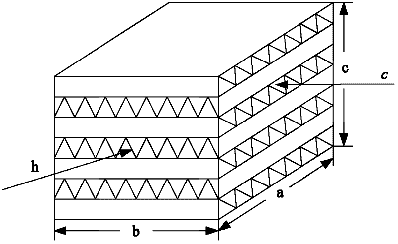
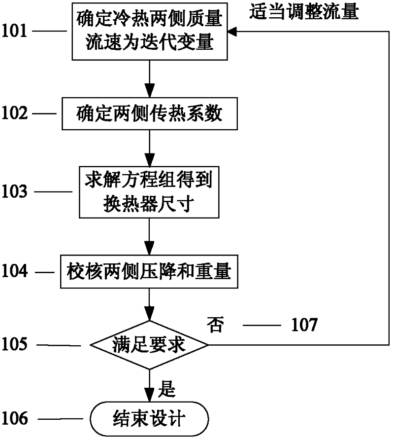
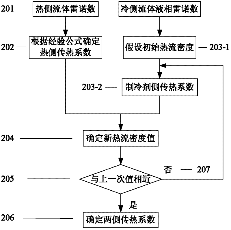

Image

  • Optimal parameter determination method for plate-fin evaporator
  • Optimal parameter determination method for plate-fin evaporator
  • Optimal parameter determination method for plate-fin evaporator

Examples


Embodiment Construction

[0014] The design methods in the prior art are mainly suitable for heat exchangers with gas flow, and with the development of industry, compact heat exchangers such as plate-fin heat exchangers are no longer limited to the flow of single-phase gas, but more and more The more it is used as evaporator and condenser, that is, the heat exchange of two-phase fluid, so this method is improved on the basis of the gas compact heat exchanger design method, and a plate suitable for two-phase flow heat exchange is proposed Method for determining the parameters of finned evaporators.

[0015] Determination of parameters in a plate-fin evaporator suitable for two-phase flow heat exchange according to an embodiment of the present invention

[0016] In the method, the mathematical model of the plate-fin evaporator that can meet the pressure drop and efficiency requirements at the same time is determined first, and its

[0017] Including:

[0018] - Neglect the thermal resistance of the col...


PUM


Abstract

The invention provides an optimal design method for a plate-fin evaporator. The method has the following beneficial effects: based on the design theory of the heat exchanger, the heat exchange coefficient of the refrigerant side of the evaporator is used instead of the heat exchange coefficient of the single phase fluid and then the size of the evaporator core is obtained by solving the equation set; the evaporator designed by the method can meet the efficiency requirement and the fluid on the two sides can simultaneously meet the pressure drop requirement; and when the equation set is solved by an iterative method, the new iteration variable needs to be reasonably selected so as to ensure the numerical solution to converge faster.

Description

technical field [0001] The invention relates to a method for determining optimal parameters of a plate-fin evaporator. Background technique [0002] Plate-fin heat exchanger has the characteristics of high heat transfer efficiency, compact structure and strong adaptability. It is not only widely used in petrochemical equipment with high air content, ethylene production and synthetic ammonia, but also in natural gas liquefaction and separation, aviation, automobile , Diesel locomotives, hydrogen helium liquefaction, refrigeration and air conditioning equipment also have huge application prospects. Its design calculation generally includes two types of problems - checking calculation and design calculation. The checking calculation is to calculate the heat exchange capacity of the existing heat exchanger or to calculate the changing working conditions; the design calculation is to determine the required heat exchange area according to the given working conditions and heat exc...

Claims


Application Information

Patent Timeline
IPC IPC(8): G06F17/50F25B39/02
Inventor 王凯董素君居世超王浚
Owner BEIHANG UNIV
Learn More