Fusion nuclear energy collection system

A collection system and nuclear energy technology, applied in the field of fusion nuclear energy collection system, can solve the problems of inability to store and utilize, large energy, etc.

Inactive Publication Date: 2012-06-20
任永斌
View PDF0 Cites 2 Cited by
  • Summary
  • Abstract
  • Description
  • Claims
  • Application Information

AI Technical Summary

Problems solved by technology

[0004] In order to overcome the shortcoming that the energy released instantly by thermonuclear fusion is too huge to be stored and utilized, the present invention proposes a fusion nuclear energy collection system to solve this problem

Method used


Image

  • Fusion nuclear energy collection system
  • Fusion nuclear energy collection system

Examples


Embodiment Construction

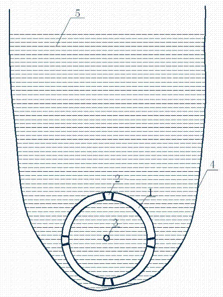
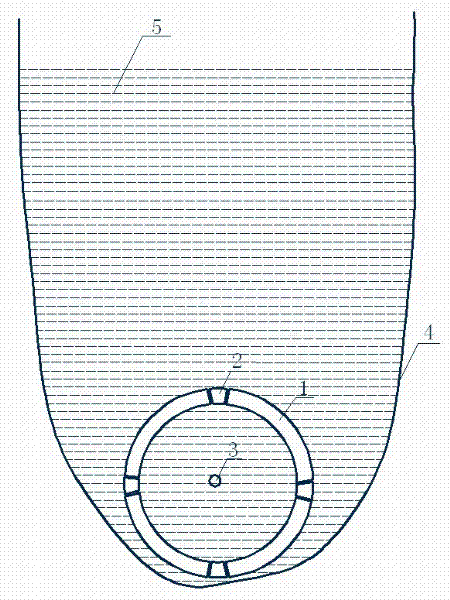
[0011] exist figure 1 Among them, we take the implementation of a fusion nuclear energy collection system as an example to further illustrate the present invention:

[0012] figure 1 It is a schematic diagram of the principle of a fusion nuclear energy collection system of the present invention. In the figure, the energy storage body 1 is a hollow cavity, and a plurality of automatic doors 2 are installed on the cavity wall. The center of the energy storage body 1 is the fusion reaction center 3, and the liquid container 4 Equipped with high-pressure liquid 5, when the fusion reaction of the fusion reaction center 3 generates huge energy, the liquid 5 contained in the energy storage body 1 will generate huge pressure instantly, the automatic door 2 has already been opened, and the liquid 5 in the energy storage body 1 Overcome the huge pressure (static pressure of liquid 5) to be discharged through the automatic door 2. When the flow rate of the liquid 5 in the energy sto...


PUM


Abstract

The invention discloses a fusion nuclear energy collection system, which consists of an energy storage body, automatic doors, a fusion reaction center, a liquid container and liquid, wherein the liquid is contained in the liquid container; the energy storage body is arranged in the liquid container; a plurality of automatic doors are arranged on the energy storage body; and the fusion reaction center is arranged in the energy storage body. By the scheme, huge uncontrollable energy generated by nuclear fusion can drive the high-pressure liquid in the energy storage body to flow out of the energy storage body to form intense pressure for human beings to use.

Description

[0001] Technical field [0002] The invention relates to a fusion nuclear energy collection system, in particular to a fusion nuclear energy collection system realized by using a container immersed in a high-pressure liquid and relying on huge energy generated by nuclear fusion to remove the high-pressure liquid therein. Background technique [0003] Nuclear fusion refers to atoms with small mass, mainly deuterium or tritium, under certain conditions (such as ultra-high temperature and high pressure), the atomic nuclei undergo mutual polymerization to generate new heavier atomic nuclei, accompanied by huge energy A form of nuclear reaction released. Thermonuclear reaction or nuclear fusion reaction is a promising new energy source at present. Thermonuclear reaction is the basis of hydrogen bomb explosion, which can generate a large amount of heat energy in an instant, but it cannot be used at present because the energy released in an instant is too large. There is no storag...

Claims


Application Information

Patent Timeline
Patent Type & Authority Applications(China)
IPC IPC(8): G21J3/00
Inventor 任永斌
Owner 任永斌
Why Eureka
Try Eureka