Plug prevention device for dust removing equipment of dusty gas in power plant and preparation method thereof

A technology for gas dust removal and power plants, which is applied in the field of air purification, dust removal and anti-blocking devices in power plants and its preparation, which can solve the problems of easy damage of filter bags, achieve the effects of improving dust removal efficiency, simple production, and reducing energy consumption

Inactive Publication Date: 2012-06-27
TIANJIN UNIVERSITY OF TECHNOLOGY
View PDF6 Cites 1 Cited by
  • Summary
  • Abstract
  • Description
  • Claims
  • Application Information

AI Technical Summary

Problems solved by technology

[0005] In view of the above situation, by adopting a special-shaped frame, the anti-blocking performance of the dust removal device in the existing power plant can be improved, and many problems such as easy damage of the filter bag caused by frequent stoppage of production, reverse blowing and vibrating dust removal can be alleviated.

Method used


Image

  • Plug prevention device for dust removing equipment of dusty gas in power plant and preparation method thereof
  • Plug prevention device for dust removing equipment of dusty gas in power plant and preparation method thereof
  • Plug prevention device for dust removing equipment of dusty gas in power plant and preparation method thereof

Examples


Embodiment 1

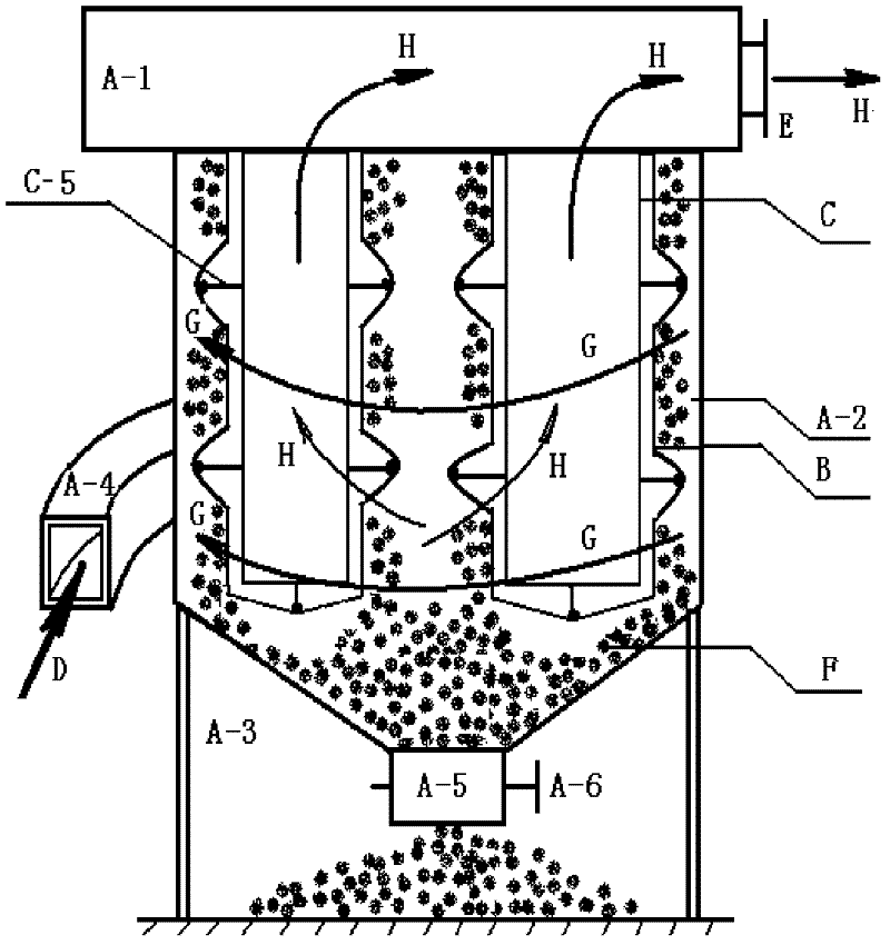
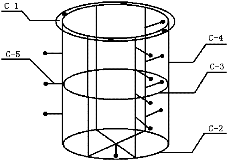
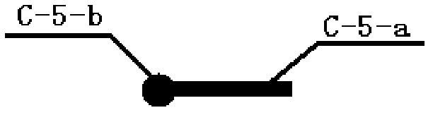
[0027] The support body C-5 in this embodiment is an independent body. Shaped frame C, such as figure 2 , image 3 As shown, it consists of the upper hoop C-1, the lower net ring C-2, the pole C-4, the fixing ring C-3 in the pole and the support body C-5. Wherein, the support body C-5 is formed by welding the support body rod C-5-a and the support body cap C-5-b, and the end surface of the support body cap C-5-b is an arc surface. The upper hoop C-1 is composed of the inner ring of the upper hoop and the outer ring of the upper hoop welded with the same center. The lower net ring C-2 is welded with two rod-shaped stainless steels in the ring to form a net ring. The connection method is to use 6 vertical rods C-4, which are evenly arranged in a barrel shape, and are connected with the inner ring of the upper hoop, the fixed ring C-3 of the vertical rod and the lower net ring C-2. In addition, 8 supports are used Body C-5 is vertically outwardly dispersed and welded on the ...

Embodiment 2

[0031] The support body C-5 in this embodiment is an independent body. For the special-shaped frame C, 12 vertical poles C-4 and 40 supports C-5 are selected. The supporting body C-5 is dispersedly welded on the vertical pole C-4 and the neutral pole fixing ring C-3. Component specifications: The height of special-shaped frame C is 2000mm. Except for the support body cap C-5-b, which is a ball with a diameter of 15mm, the rest of the components are rod-shaped stainless steel with a diameter of 8mm; among them, the inner ring of the upper hoop, the lower net ring C-2 and the middle fixing ring C-3 of the vertical rod The diameters are all 1000mm; the lengths of the vertical poles C-4 are all 2000mm; the lengths of the support poles C-5-a are 100mm. Others are with embodiment 1.

Embodiment 3

[0033] Support C-5 is not independent. This scheme saves the welding process of making the support body C-5 and its connection with other parts; that is, the rod body material is used, and according to the specification and shape of the support body C-5, it is respectively connected with the vertical rod C-4 and the middle fixing ring of the vertical rod The shape of C-3 or the lower end mesh ring C-2 is bent together to form an integral part, so that the vertical rod C-4, the middle fixed ring C-3 of the vertical rod or the lower end mesh ring C-2 are respectively formed with The convex upright rod of the support body C-5, the fixed ring in the convex upright rod or the net ring at the lower end of the convex shape. The length of the convex vertical rod, the diameters of the fixed ring in the convex vertical rod and the net ring at the lower end of the convex shape are all constant. Others are with embodiment 1.


PUM

PropertyMeasurementUnit
lengthaaaaaaaaaa
lengthaaaaaaaaaa

Abstract

A plug prevention device for dust removing equipment of dusty gas in a power plate and a preparation method thereof belong to technology of plug prevention of dusty gas purification equipment, especially relate to air dust removing and plug prevention devices and technology of the power plant and resolve the problems that in existing dust removing dust device of the power plant, air flow channels are prone to be blocked by powder, shutdown is frequently required to vibrate and remove dust, a filter bag is prone to be damaged and the like. The technical scheme is that a special-shaped framework (C) composed of an upper hoop (C-1), a vertical rod middle fixing ring (C-3), a lower end net ring (C-2), a vertical rod (C-4) and a support body (C-5) are adopted. The plug prevention device for dust removing equipment of dusty gas in the power plate and the preparation method are ingenious in design, simple and practical, convenient to use and free of changing existing dust removing device in the power plant. The problem of plug prevention of dust removing equipment of dusty gas in the power plate can be resolved, rate of plug of air flow channels of the existing dust removing device in the power plant is reduced, dust removing efficiency is improved, equipment energy consumption and production cost are reduced, significance is brought to high efficiency, energy saving, noise reduction and environment protection, and economic and social benefits are brought.

Description

technical field [0001] The invention belongs to an anti-blocking technology of dust-containing gas purification equipment in a power plant, and in particular relates to an air purification and dust-removing anti-blocking device in a power plant and a preparation method thereof. technical background: [0002] The anti-blocking problem of dust-containing gas dust removal and purification equipment in power plants is a worldwide problem. At present, the dust removal equipment of power plants basically does not have the function of anti-blocking. When the dust removal and purification equipment is working, the dust-containing gas passes through the filter bag, and the dust material continues to adhere to the overall outer wall of the filter bag. With the thickening of dust and material deposition, it is easy to block the airflow channel of the filter bag, resulting in poor airflow transportation. The energy consumption of the motor increases, the noise increases, and even the m...

Claims


Application Information

Patent Timeline
Patent Type & Authority Applications(China)
IPC IPC(8): B01D46/42B01D46/04
Inventor 王喆
Owner TIANJIN UNIVERSITY OF TECHNOLOGY
Why Eureka
Try Eureka