Plate back press forming method utilizing displacement control mode

A technology of displacement control and pressure forming, which is applied in the field of plate forming, can solve the problems of large deformation and complex shape, and achieve the effect of large deformation

Inactive Publication Date: 2012-06-27
HARBIN INST OF TECH
View PDF6 Cites 4 Cited by
  • Summary
  • Abstract
  • Description
  • Claims
  • Application Information

AI Technical Summary

Problems solved by technology

[0004] In order to solve the problem that the existing plate part forming method cannot form parts with large deformation and complex shape, the present invention further proposes a pressure forming method for the back of the plate using a displacement control method

Method used


Image

  • Plate back press forming method utilizing displacement control mode
  • Plate back press forming method utilizing displacement control mode
  • Plate back press forming method utilizing displacement control mode

Examples


specific Embodiment approach 1

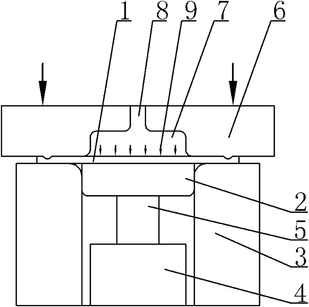
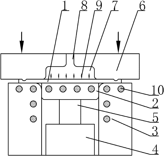
[0013] Specific implementation mode one: combine Figure 1 to Figure 8 To illustrate this embodiment, the specific steps of a method for pressurizing the back of a plate using a displacement control method described in this embodiment are as follows:

[0014] Step 1, placing the slab 1 to be formed on the die base 2, adjusting the position of the plunger rod 5 of the hydraulic cylinder 4, so that the upper surface of the die 3 contacts the lower surface of the slab 1 to be formed;

[0015] Step 2, the pressing plate 6 moves downward to press the slab 1 to be formed on the upper surface of the die holder 2, and the lower surface of the pressing plate 6 and the upper surface of the slab 1 to be formed form a closed cavity 7;

[0016] Step 3: Inject the high-pressure fluid medium 9 into the cavity 7 through the through hole 8 opened above the pressure plate 6;

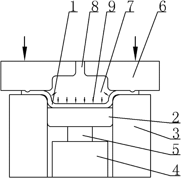
[0017] Step 4, by controlling the plunger rod 5 of the hydraulic cylinder 4 to move down, the die 3 and the slab to be...

specific Embodiment approach 2

[0020] Specific implementation mode two: combination figure 1 , figure 2 , Figure 5 with Image 6 To illustrate this embodiment, the high-pressure fluid medium 9 in Step 3 of a method for pressurizing the backside of a plate using a displacement control method described in this embodiment is a liquid high-pressure fluid medium 9 of 1-200Mpa. Other components and connections are the same as those in the first embodiment.

specific Embodiment approach 3

[0021] Specific implementation mode three: combination figure 1 , figure 2 , Figure 5 with Image 6 To illustrate this embodiment, the high-pressure fluid medium 9 in Step 3 of a method for pressurizing the backside of a plate using a displacement control method described in this embodiment is a gaseous high-pressure fluid medium 9 of 1-100 Mpa. Other components and connections are the same as those in the first embodiment.


PUM


Abstract

The invention relates to a plate forming method, in particular to a plate back press forming method utilizing a displacement control mode, which solves the problem that the existing plate part forming method is incapable of forming parts high in deformation and complicated in shape. The plate back press forming method includes steps of placing a to-be-formed plate blank on a die holder, regulating position of a plunger rod of a hydraulic cylinder until the upper surface of a die contacts with the lower surface of the to-be-formed plate blank; pressing the to-be-formed plate blank onto the upper surface of the die holder by downward motion of a press plate and reserving a closed cavity between the lower surface of the press plate and the upper surface of the to-be-formed plate blank; injecting high-pressure fluid medium into the cavity though a through hole arranged above the press plate; and moving the die and the to-be-formed plate blank downwards synchronously until the to-be-formed plate blank is formed completely by controlling the plunger rod of the hydraulic cylinder. The plate back press forming method is used for the plate expansion process or the plate drawing forming process.

Description

technical field [0001] The invention relates to a sheet material forming method, in particular to a sheet material back pressure forming method in a displacement control mode. Background technique [0002] Bulging and deep drawing are the two main forming methods of sheet metal parts. The difference between bulging and deep drawing is that the material in the flange area does not move to the mold cavity during bulging, but the material in the flange area will flow significantly to the mold cavity during deep drawing. When forming, a rigid punch or a fluid medium can be used as a punch. Compared with the rigid punch, when the fluid medium is used as the punch, the plate in the forming area will be subjected to uniformly distributed pressure, and there will be no stress concentration phenomenon. The deformation of the plate is relatively uniform and the formability is good. However, no matter whether a rigid punch or a fluid medium is used as the punch, the material in the m...

Claims


Application Information

Patent Timeline
Patent Type & Authority Applications(China)
IPC IPC(8): B21D26/025
Inventor 苑世剑何祝斌
Owner HARBIN INST OF TECH
Why Eureka
Try Eureka