Swingable deflection deformation compensation device for ram

A flexural deformation and compensation device technology, applied in other manufacturing equipment/tools, manufacturing tools, etc., can solve the problems of flexural deformation compensation, increase the axial movement error of the main shaft, etc., and achieve a good compensation effect.

Inactive Publication Date: 2012-06-27
YANSHAN UNIV
View PDF7 Cites 6 Cited by
  • Summary
  • Abstract
  • Description
  • Claims
  • Application Information

AI Technical Summary

Problems solved by technology

This kind of compensation method usually compensates the ram protruding horizontally, but cannot compensate the deflection deformation of the ram with positive and negative swing angles i

Method used


Image

  • Swingable deflection deformation compensation device for ram
  • Swingable deflection deformation compensation device for ram
  • Swingable deflection deformation compensation device for ram

Examples


Embodiment Construction

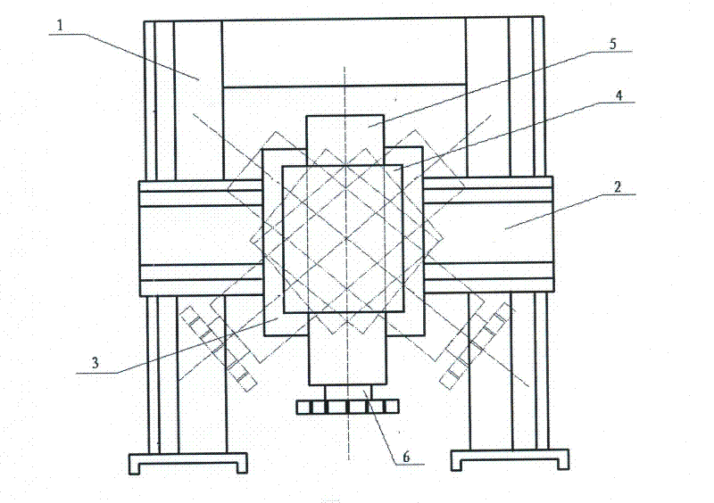
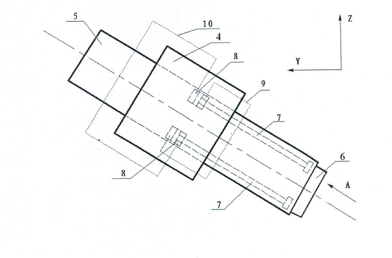
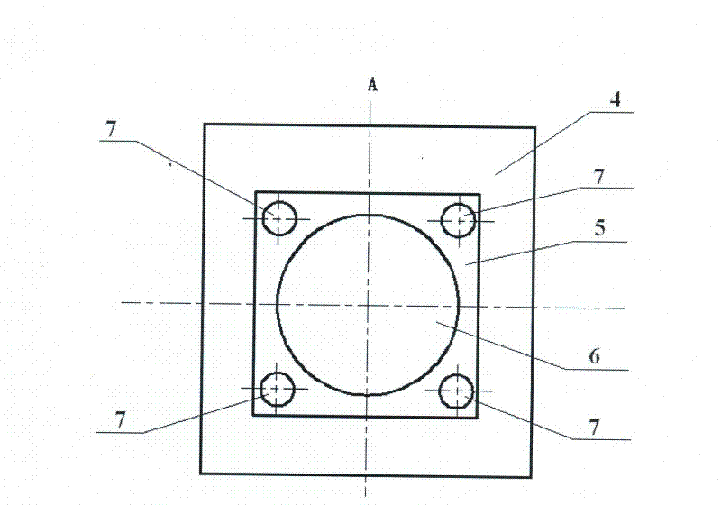
[0013] exist figure 1 In the schematic diagram of the installation position and movement of a swingable ram deflection compensation device shown, the gantry 1 is a gantry-type frame structure composed of left and right columns and connecting beams, and the beam 2 is installed on the left and right columns of the gantry. The crate 3 is installed on the beam, which is driven and positioned by the screw nut pair and the guide rail pair, and is tightly fixed by the pressure plate and the beam. The ram turntable 4 is installed on the slide crate and connected by bearings. The ram 5 Installed on the above-mentioned ram turntable, the main shaft 6 is installed inside the ram. Such as figure 2 , 3 The four same force application rods 7 shown are divided into upper and lower groups, which are respectively installed on the upper side and the lower side of the ram. One group is a pull rod, and the other group is a push rod. The four force rods are arranged along the main axis of the r...


PUM


Abstract

The invention relates to a swingable deflection deformation compensation device for a ram. The upper side and the lower side in the ram are respectively provided with two groups of force application rods, namely one group of pull rods and one group of push rods. Four force application rods are distributed along the central line of a spindle of the ram in a central symmetry mode and respectively arranged at four corners of the cross section perpendicular to the surface of the ram. Four series supercharged type hydraulic oil cylinders are respectively connected with the four force application rods, oil inlets of the four oil cylinders are respectively connected with the same oil inlet loop, oil outlets of the four oil cylinders are respectively connected with the same oil outlet loop, and the oil pressure and flow of the four multistage series supercharged oil cylinders are controlled by corresponding hydraulic control loops so that adjustment of acting force of corresponding force application rods and conversion between push acting force and pull acting force can be achieved. The swingable deflection deformation compensation device for the ram can adjust the size and direction of the acting force of the hydraulic force application rods in real time, additional axial deformation can not happen, and comprehension effects are good.

Description

technical field [0001] The invention belongs to the technical field of mechanical manufacturing, and in particular relates to a turning and milling processing device. Background technique [0002] A four-axis or five-axis linkage turning and milling machining center usually consists of a bed, a gantry, a beam, a worktable, a sliding crate, a turntable, a ram and other components. As the main working part of the machine tool, the ram is installed on the turntable and can perform telescopic movement along the guide rail on the turntable. The main shaft is installed inside the ram, and the tool is driven by the rotation of the main shaft and the up and down movement of the ram to cut the workpiece. When the turntable rotates on the sliding crate, it can drive the ram on it to swing in the vertical plane (B axis). When the ram swings in the vertical plane, an angle is formed between the axis of the main shaft of the ram and the vertical line in the vertical plane. Stretch stat...

Claims


Application Information

Patent Timeline
IPC IPC(8): B23Q23/00
Inventor 吴凤和赵峰兵江崇民
Owner YANSHAN UNIV
Why Eureka
Try Eureka