Three-finger capture positioning mechanism

A positioning mechanism and single-finger technology, applied in the direction of manipulators, chucks, manufacturing tools, etc., can solve the problems of small capture range and weak correction ability, and achieve the effect of simple and reliable structure, strong guiding ability, and large capture range

Inactive Publication Date: 2012-06-27
HARBIN INST OF TECH
View PDF4 Cites 9 Cited by
  • Summary
  • Abstract
  • Description
  • Claims
  • Application Information

AI Technical Summary

Problems solved by technology

[0003] The purpose of the present invention is to provide a three-finger capture positioning mechanism to solve the problem that the capture target of the robot is in a multi-degree-of-freedom floating state, and the existing robot terminal docking device has a small capture range and weak correction ability

Method used


Image

  • Three-finger capture positioning mechanism
  • Three-finger capture positioning mechanism
  • Three-finger capture positioning mechanism

Examples


specific Embodiment approach 1

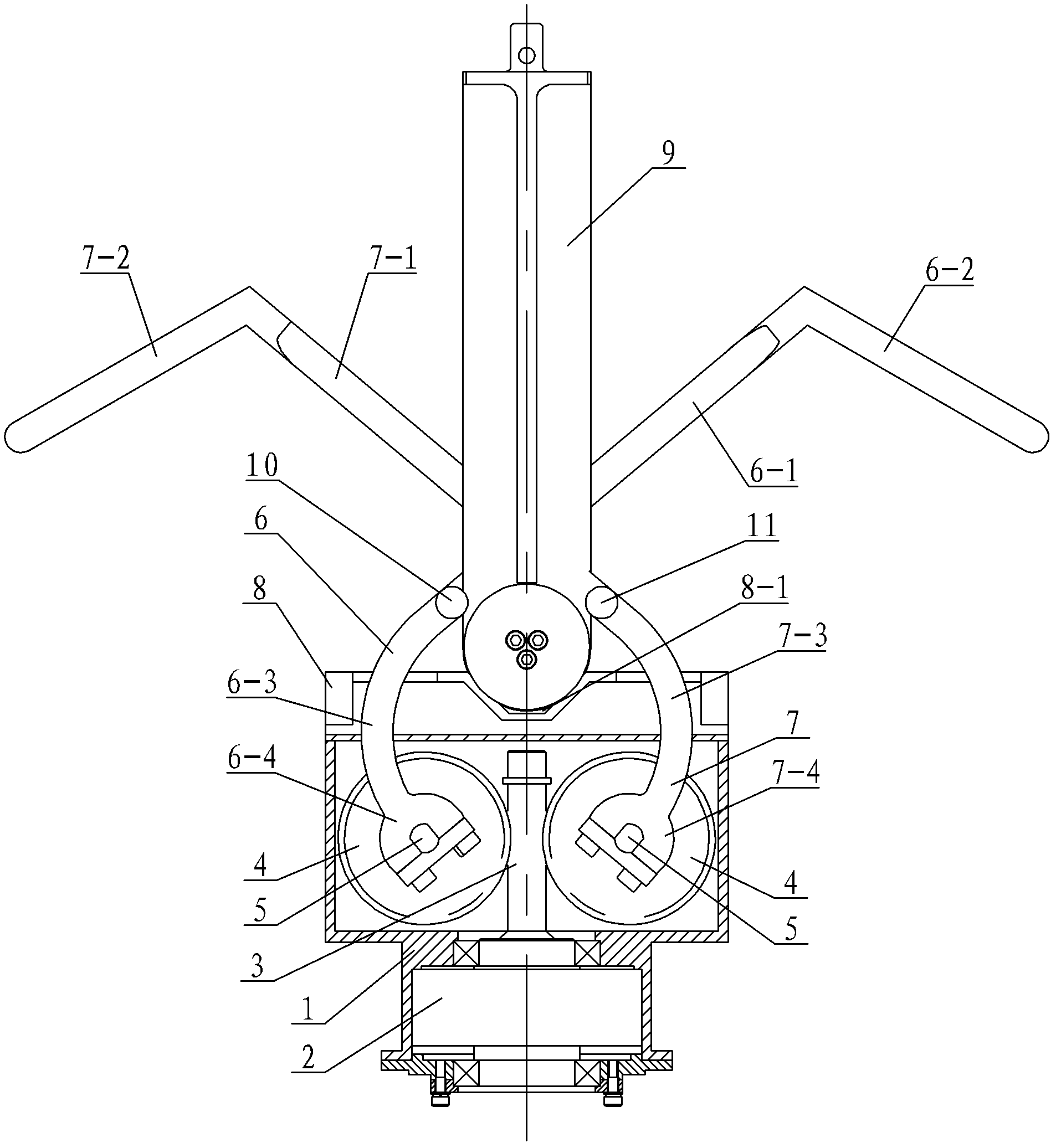
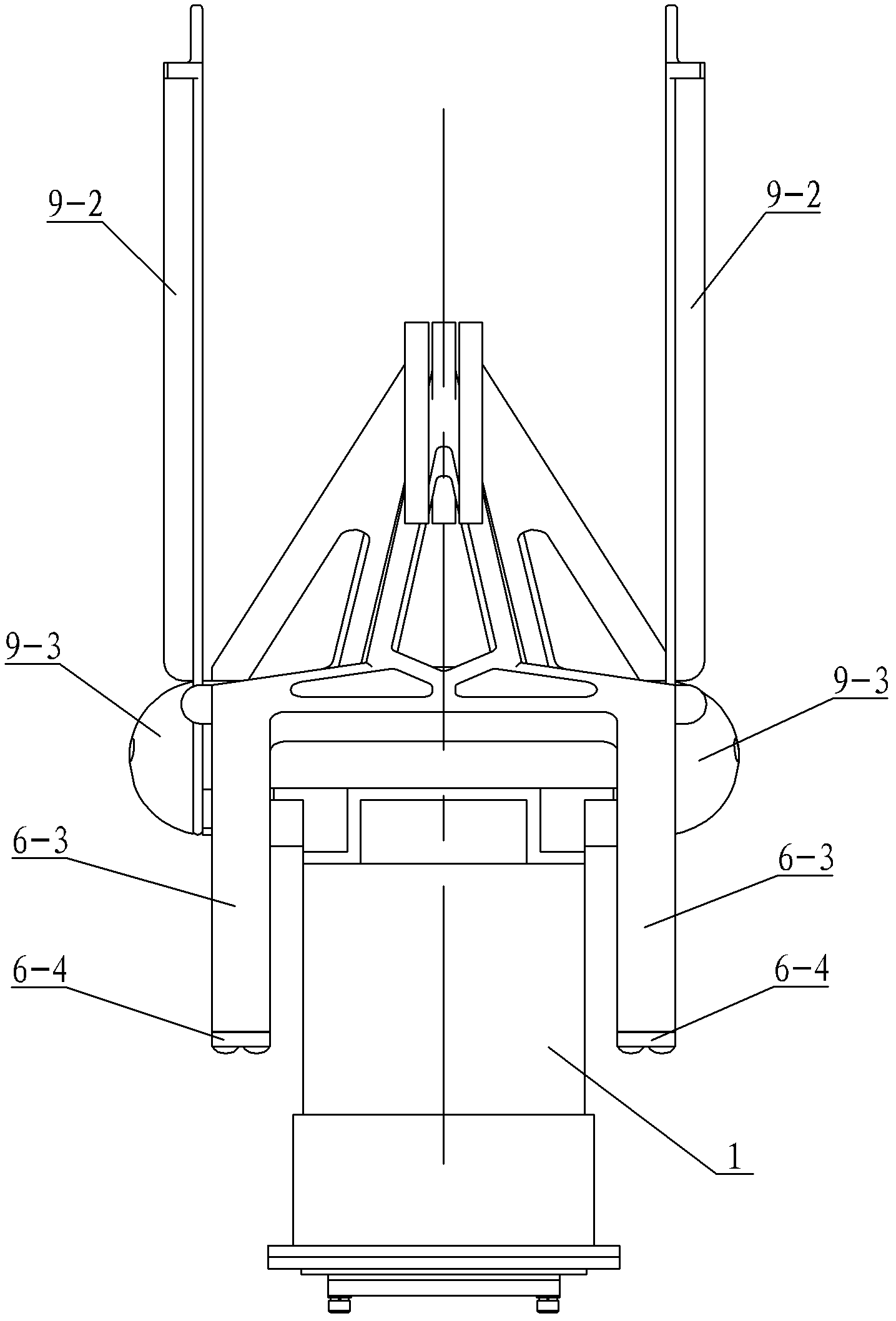
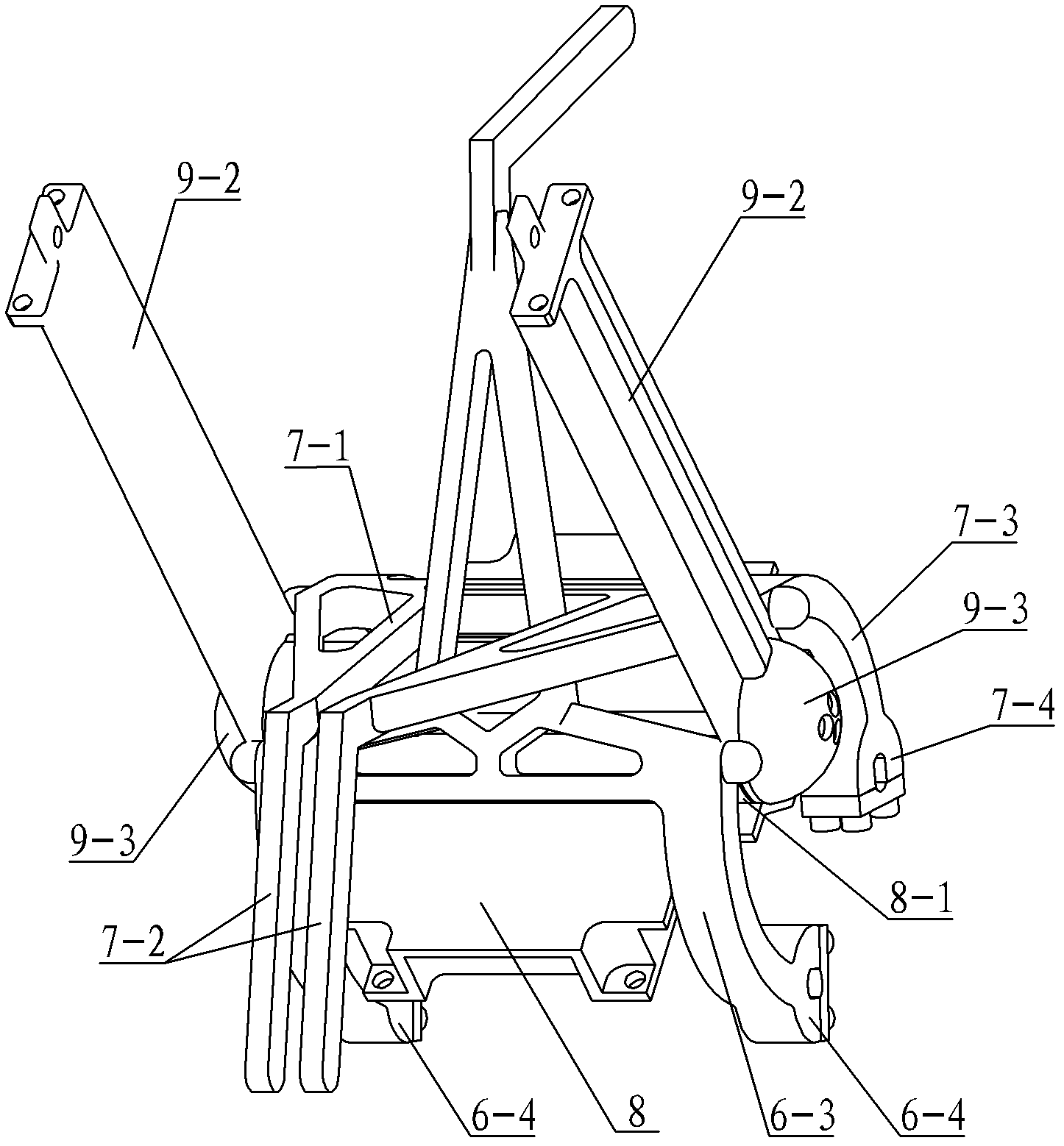
[0007] Specific implementation mode one: combine Figure 1 to Figure 7 Describe this embodiment, this embodiment includes housing 1, motor 2, worm shaft 3, two worm wheels 4, two worm shafts 5, single finger 6, double fingers 7, fixed plate 8 and capture interface device 9, worm shaft 3 is installed in the housing 1 through bearings, the input end of the worm shaft 3 is connected with the output shaft of the motor 2, two worm gears 4 are symmetrically arranged on both sides of the worm shaft 3, and both worm gears 4 are connected to the The teeth mesh, the worm gear 4 is installed on the worm gear shaft 5, the two ends of the worm gear shaft 5 are installed on the housing 1 through bearings, the single finger 6 is composed of a single finger connecting arm 6-1, a single finger capture head 6-2, two single finger The finger curved arm 6-3 is composed of two single-finger connectors 6-4, the single-finger capture head 6-2 is arranged on the upper end of the single-finger connect...

specific Embodiment approach 2

[0008] Specific implementation mode two: combination figure 1 with Figure 5 Describe this embodiment, the difference between this embodiment and specific embodiment 1 is that it also adds a single-fingered positioning post 10 and a double-fingered positioning post 11, the single-fingered positioning post 10 is arranged in parallel with the V-shaped groove 8-1, and the single-fingered positioning The positioning post 10 is installed on the single-finger connecting arm 6-1, the two-finger positioning post 11 is arranged parallel to the V-shaped groove 8-1, and the two-finger positioning post 11 is installed on the two-finger connecting arm 7-1. The handle 9-1 is compressed by the single-finger positioning post 10 and the double-finger positioning post 11. Other components and connections are the same as those in the first embodiment.

specific Embodiment approach 3

[0009] Specific implementation mode three: combination figure 1 with Figure 5 To describe this embodiment, the double-fingered positioning post 11 and the single-fingered positioning post 10 of this embodiment are arranged symmetrically with respect to the central line P-P of the V-shaped groove 8-1. Other components and connections are the same as those in the second embodiment.

[0010] The working principle of the present invention: when in use, the housing 1 is installed on the end effector of the robot, and the two brackets 9-2 on the capture interface device 9 are connected with the capture target; the motor 2 drives the worm shaft 3 to rotate, and the two worm gears 4 rotates thereupon, and two worm gears 4 drive single-finger connector 6-4 and double-finger connector 7-4 to rotate respectively by worm gear shaft 5 thereon, and single-finger capture head 6-2 and two double-finger capture head 7 -2 Envelope the handle 9-1 on the capture interface device 9 back, guide ...


PUM


Abstract

A three-finger capture positioning mechanism relates to a robot tail end butting device and aims to solve the problems of small capture range and low correction capability of an existing robot tail end butting device. A worm shaft is mounted in a casing, an input end of the worm shaft is connected with an output shaft of a motor, two worm gears are meshed with teeth on the worm shaft and mounted on worm gear shafts, a single finger and double fingers are symmetric about the axis of the worm shaft, two single-finger connectors are mounted on one worm gear shaft, two double-finger connectors are mounted on the other worm gear shaft, a central line of a single-finger connecting arm and a central line of a double-finger connecting arm are positioned in the same plane, a V-shaped groove is arranged on a fixed plate, the fixed plate is fixedly connected with the casing, the V-shaped groove is positioned among the single finger and double fingers, the central line of the V-shaped groove is overlapped with the axis of the worm shaft, a handle on a capture joint device after capture is arranged in the V-shaped groove, and a V-shaped surface matched with the V-shaped groove is arranged on the handle. The three-finger capture positioning mechanism is used for a space robot to capture a floating target.

Description

technical field [0001] The invention relates to a robot terminal docking device. Background technique [0002] With the continuous development of robot technology and the expansion of robot application fields, it is required that the robot can work in the space environment and complete the docking and capture of floating targets. Due to the characteristics of uncertain position and attitude of the captured target in space, it is necessary to have a capture and docking device with a large tolerance range and capable of correcting position and attitude deviation. At present, the end effectors of ordinary robots and the captured targets are in a relatively fixed pose state, regardless of whether they have special docking devices or not, and it is impossible to capture targets with uncertain poses. Therefore, there is a need for a docking device with a larger pose tolerance and higher positioning and posture determination to assist the robot in completing space docking capture....

Claims


Application Information

Patent Timeline
Patent Type & Authority Applications(China)
IPC IPC(8): B25J15/08
Inventor 朱映远倪风雷王志国史士财孙奎刘宏
Owner HARBIN INST OF TECH
Why Eureka
Try Eureka