Corrosive agent for displaying 9% Cr steel original austenite grain boundary and application thereof

A technology of austenite grain boundaries and corrosive agents, which is applied in the preparation of test samples, etc., can solve the problems of invisible grain boundaries, influence on grain size rating, and inconvenience of material detection and analysis, and achieve good results

Active Publication Date: 2012-06-27
SHANGHAI BOILER WORKS
View PDF3 Cites 32 Cited by
  • Summary
  • Abstract
  • Description
  • Claims
  • Application Information

AI Technical Summary

Problems solved by technology

In the metallographic examination of 9% Cr steel, the currently used etchant can only corrode the structure, but the grain boundary is basically invisible, which seriously affects the r

Method used


Image

  • Corrosive agent for displaying 9% Cr steel original austenite grain boundary and application thereof
  • Corrosive agent for displaying 9% Cr steel original austenite grain boundary and application thereof
  • Corrosive agent for displaying 9% Cr steel original austenite grain boundary and application thereof

Examples


Embodiment 1

[0021] 3g FeCl 3 Put it in a container, then add 0.5g of picric acid, then add 6ml of hydrochloric acid (36% by weight concentration), add 75ml of water, then add 1.5g of sodium dodecylsulfonate, and mix well to obtain a corrosive agent. Process the 9% Cr steel into a sample to be corroded. After polishing, at room temperature, use a cotton ball dipped in corrosive agent to gently rub the metal surface for about 11 seconds, clean it with water, rinse it with alcohol, and dry it with a hair dryer. The metallographic structure was observed with a metallographic microscope.

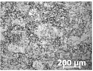
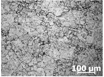
[0022] The grain boundary morphology of the sample is as figure 1 and image 3 As shown, among them, figure 1 is the grain boundary morphology observed by a metallographic microscope (×100), image 3 It is the grain boundary morphology observed by metallographic microscope (×200).

Embodiment 2

[0024] 2g FeCl 3 Put it in a container, then add 0.2g of picric acid, then add 4ml of hydrochloric acid (36% concentration by weight), add 60ml of water, then add 1.0g of sodium dodecylsulfonate, and mix well to obtain a corrosive agent. Process the 9% Cr steel into a sample to be corroded. After polishing, at room temperature, use a cotton ball dipped in corrosive agent to gently rub the metal surface for about 13 seconds, clean it with water, rinse it with alcohol, and dry it with a hair dryer. The metallographic structure was observed with a metallographic microscope.

[0025] The grain boundary morphology of the sample is as Figure 5 As shown, among them, Figure 5 It is the grain boundary morphology observed by metallographic microscope (×100).

Embodiment 3

[0027] First add 4g FeCl 3 In the container, add 0.5g of picric acid, then add 8ml of hydrochloric acid (36% concentration by weight), add 80ml of water, then add 2.0g of sodium dodecylsulfonate, and mix well to obtain a corrosive agent. Process the 9% Cr steel into a sample to be corroded. After polishing, at room temperature, use a cotton ball dipped in corrosive agent to gently rub the metal surface for about 10 seconds, clean it with water, rinse it with alcohol, and dry it with a hair dryer. The metallographic structure was observed with a metallographic microscope.

[0028] The grain boundary morphology of the sample is as Figure 6 As shown, among them, Figure 6 It is the grain boundary morphology observed by metallographic microscope (×100).

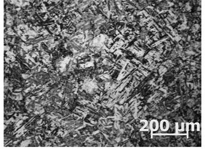
[0029] The same mixed crystal sample was corroded with conventional etchant Vickers reagent, the structure was clear, but the grain boundaries were not obvious, and the appearance was as follows: figure 2 and Figure 4 sho...


PUM


Abstract

The invention discloses a corrosive agent for displaying 9% Cr steel original austenite grain boundary and an application thereof. The corrosive agent is prepared by fully mixing the following components of: 60-80ml of H2O, 4-8ml of 36 wt% HCl, 2-4g of FeCl3, 0.2-0.5g of picric acid, and 1.0-2.0g of sodium dodecanesulphonate. The corrosive agent provided by the invention can be used as a reagent for 9% Cr steel grain boundary to clearly display the original austenite grain boundary of large crystal grain, large and small mixed crystal grain and small crystal grain of a sample. Under 100 times, it is easy to carry out grain size rating and the effect is good.

Description

technical field [0001] The invention relates to an etchant, in particular to an etchant showing grain boundaries of 9% Cr steel prior austenite and application thereof. Background technique [0002] The size of metal grains has a decisive influence on its mechanical properties at room temperature and high temperature. In the analysis of metallographic structure, the evaluation of grain size is very important. The high-temperature pressure-bearing components of supercritical units (including main steam pipes, reheating hot section pipes and high-temperature headers, etc.) are mainly made of 9% Cr steel. However, when performing metallographic examination on 9% Cr steel, the currently used etchant can only corrode the structure, and the grain boundary is basically invisible, which seriously affects the rating of the grain size. This phenomenon is more prominent in samples with mixed crystals and large grains, which brings a lot of inconvenience to the material detection and ...

Claims


Application Information

Patent Timeline
IPC IPC(8): C23F1/28G01N1/32
Inventor 李强卢小莉李宝虎张波
Owner SHANGHAI BOILER WORKS
Why Eureka
Try Eureka