General switch detector

A detector and switch technology, applied in the field of general switch detectors, can solve the problems of increasing tooling design and processing time, not being able to observe the switch module channel in real time, complicated test process, etc., and achieve the effect of improving test efficiency

Active Publication Date: 2014-02-19
BEIJING AEROSPACE MEASUREMENT & CONTROL TECH
View PDF5 Cites 0 Cited by
  • Summary
  • Abstract
  • Description
  • Claims
  • Application Information

AI Technical Summary

Problems solved by technology

Usually, when conducting the on-off state of the switch module, it is necessary to connect the multimeter and the switch module to form a test system. The on-off state of the switch module channel is tested separately. This test method is suitable for mass production. The burn-in test and inspection test in the process are more suitable, but because the test process of this test method is complicated and the test time is long, it is impossible to observe in real time whether the on-off state of the switch module channel is normal during the debugging and test process
In addition, this test method requires different test fixtures, test cables and automatic test procedures for different types of switch modules, which not only increases the design and processing time of the fixtures, but also increases the cost.
[0003] In the process of testing, for various switch modules, it is necessary to design different transfer cables and test fixtures. In this way, when directly testing through the lead-out cables, it is necessary to use an instrument to measure the on-off status of each channel of the switch module one by one. To verify that only one switch is closed or disconnected at the same time, so the test efficiency is relatively low

Method used


Image

  • General switch detector
  • General switch detector
  • General switch detector

Examples


Embodiment Construction

[0029] The present invention will be described in detail below with reference to the accompanying drawings and examples.

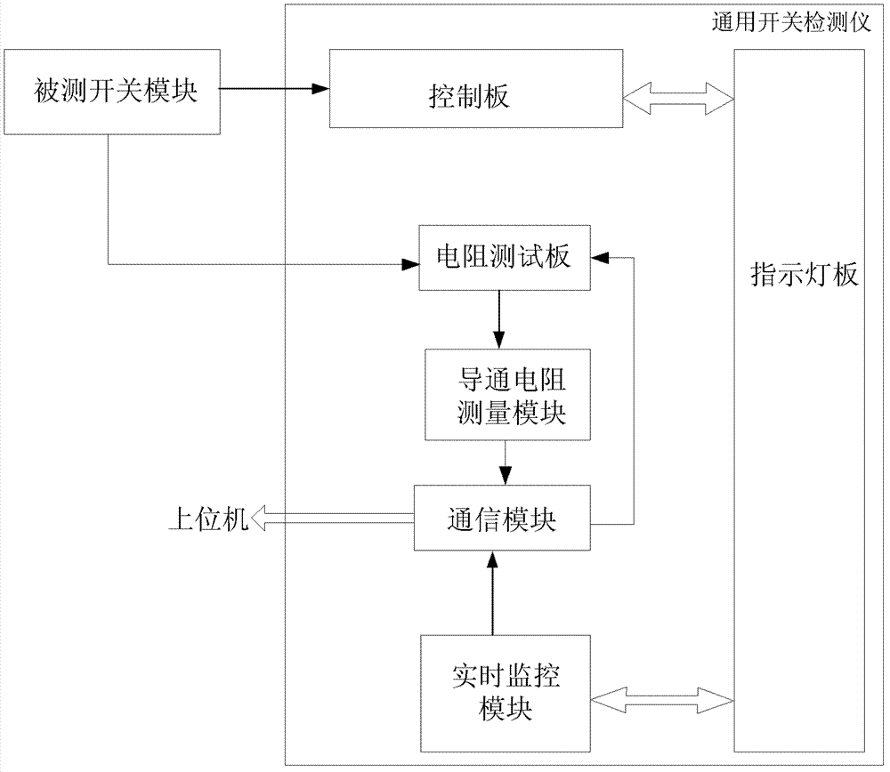
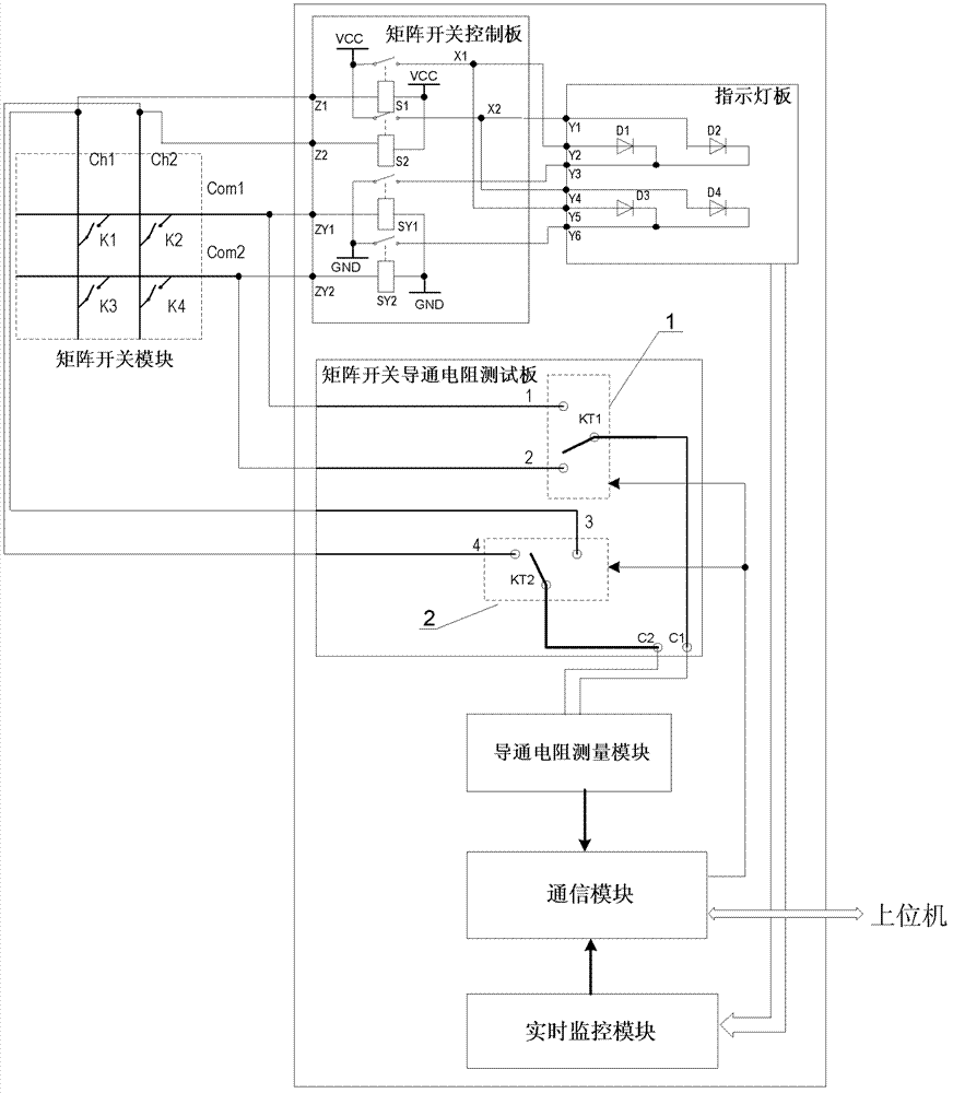
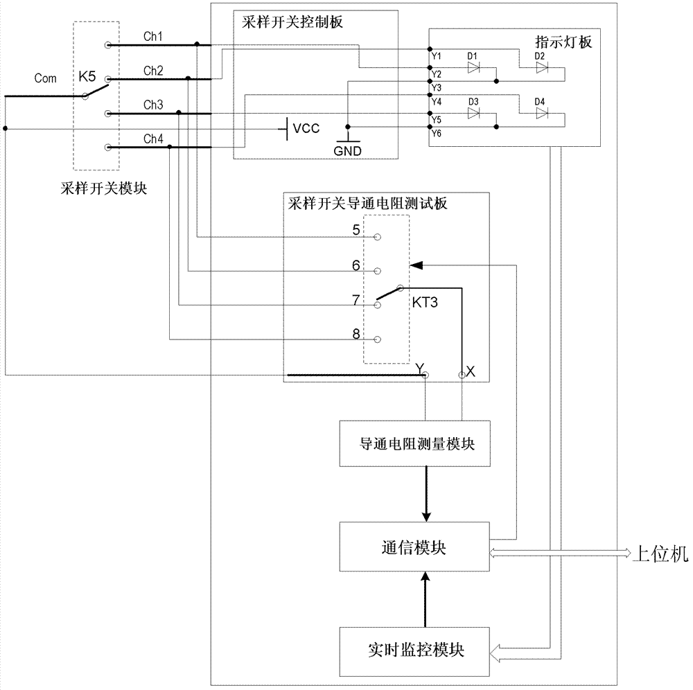
[0030] The invention provides a universal switch detector, including a control board, an indicator board, a resistance test board, a conduction resistance measurement module, a communication module, and a real-time monitoring module, wherein:

[0031] The connection relationship of each component of the detector is as follows:

[0032] The external switch module to be tested is connected to the indicator board through the control board and the on-resistance measurement module through the resistance test board. The communication module is connected to the on-resistance measurement module, the real-time monitoring module and the resistance test board respectively. The indicator board is connected, and the external host computer exchanges information with the communication module.

[0033] Both the control board and the resistance test board are replaceable ...


PUM


Abstract

The invention discloses a general switch detector, so that an objective that testing efficiency of a switch module is improved can be achieved. The general switch detector comprises a control panel, an indicating lamp plate, a resistance test board, a conduction resistance measurement module, a communication module and a real-time monitoring module. The control panel controls corresponding light emitting diodes inside the indicating lamp plate according to switch states of all switches. The real-time monitoring module records response states of all the light emitting diodes and transmits the response states to the communication module. Under control of the communication module, the resistance test board employs a one-out-of-multiple circuit to carry out gating on a detected switch and obtain resistance values at two ends of the gating switch. The conduction resistance measurement module obtains the resistance values of the gating switch, carries out calculation to obtain a voltage value and carries out A / D conversion, and simultaneously transmitting the processed voltage value to the communication module. And the communication module receives a switch control instruction of a host computer, the light emitting diode response states and the voltage values, carries out calculation to obtain a conduction resistance value and controls a switching state of the one-out-of-multiple circuit, and simultaneously sending the light emitting diode response states and the conduction resistance value to the host computer.

Description

technical field [0001] The invention belongs to the field of test equipment, and in particular relates to a universal switch detector. Background technique [0002] As the application range of switch modules becomes wider and wider, the requirements for testing efficiency in the mass production process of switch modules are further increased. Usually, when conducting the on-off state of the switch module, it is necessary to connect the multimeter and the switch module to form a test system. The on-off state of the switch module channel is tested separately. This test method is suitable for mass production. The burn-in test and inspection test in the process are more suitable, but due to the complicated test process and long test time of this test method, it is impossible to observe in real time whether the on-off status of the switch module channel is normal during the debugging and test process. In addition, this test method requires different test tooling, test cables and...

Claims


Application Information

Patent Timeline
Patent Type & Authority Patents(China)
IPC IPC(8): G01R31/327
Inventor 赵砚博刘洋毛进张晓李静王聪黄月芳
Owner BEIJING AEROSPACE MEASUREMENT & CONTROL TECH
Why Eureka
Try Eureka