Permanent magnet type vacuum circuit breaker

A vacuum circuit breaker, permanent magnet technology, applied in the direction of high-voltage air circuit breakers, circuits, electrical components, etc., can solve problems such as immature technology, difficult technology, complex structure, etc., to improve mechanism reliability, reduce costs, The effect of reducing height

Inactive Publication Date: 2012-06-27
ANHUI YUTENG VACUUM ELECTRICAL
View PDF5 Cites 9 Cited by
  • Summary
  • Abstract
  • Description
  • Claims
  • Application Information

AI Technical Summary

Problems solved by technology

The former is technically difficult and immature, and it is difficult to realize three-phase synchronous action, so it cannot be applied in occasions where the product price is low; the latter needs to increase the guide device to realize linear drive, which is not only complex in structure, high in cost, but also reliable in operation performance and stability can not be compared with linear drive

Method used


Image

  • Permanent magnet type vacuum circuit breaker
  • Permanent magnet type vacuum circuit breaker

Examples


Embodiment 1

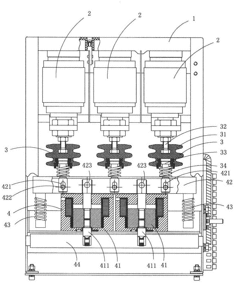
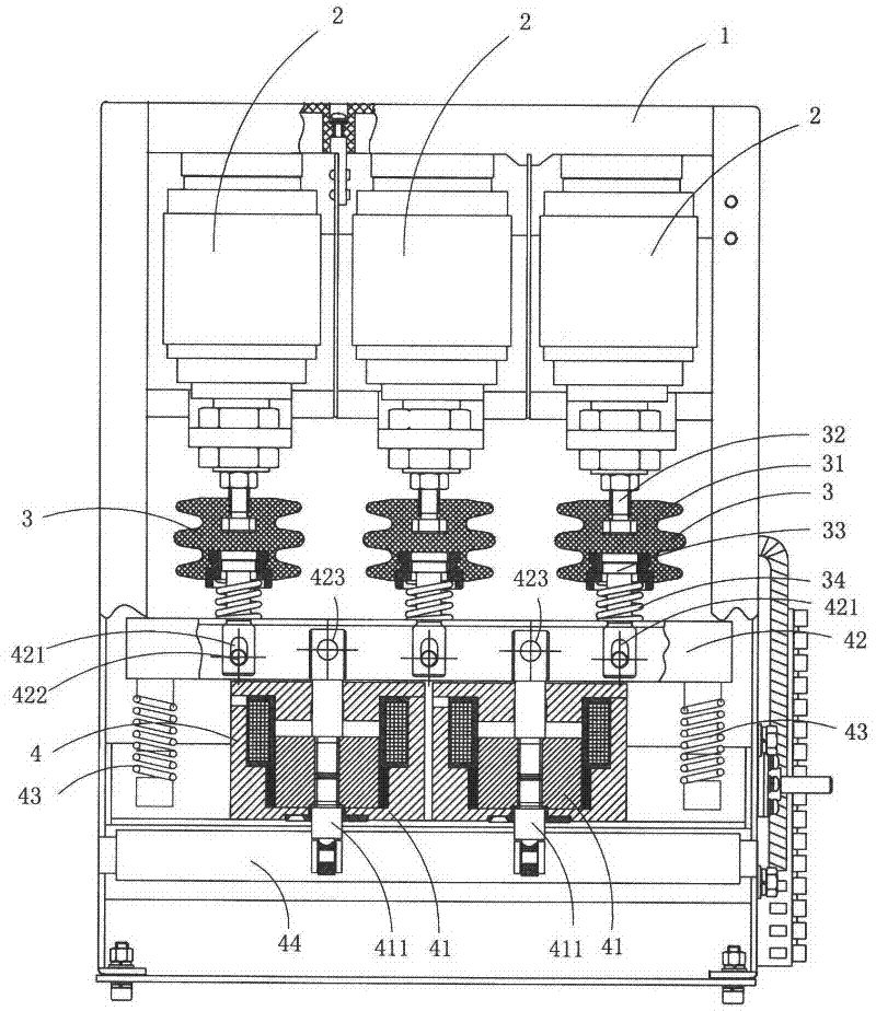
[0018] figure 1 It is a structural schematic diagram of the present invention, showing a specific embodiment of the present invention.

[0019] This embodiment is a permanent magnet vacuum circuit breaker, see figure 1 As shown, it includes a frame 1, three vacuum switch tubes 2 arranged on the frame 1, an insulating pull rod assembly 3 connected to the moving contact in each vacuum switch tube 2, and an insulating pull rod assembly 3 for driving the insulating pull rod assemblies 3 to move synchronously. The permanent magnet drive device 4.

[0020] The permanent magnet drive mechanism 41 includes two permanent magnet drive mechanisms 41 each provided with a drive shaft 411, a linkage rod 42 fixedly connected to the two drive shafts 411, two auxiliary opening springs 43, and a synchronous shaft 44; the linkage rod 42 is also connected to the three insulating pull rod assemblies 3; the two permanent magnet drive mechanisms 41 drive the linkage rod 42 to reciprocate through t...

Embodiment 2

[0030] This embodiment is basically the same as Embodiment 1, except that the three switch tubes are located directly above the linkage rod 42, and the two drive shafts 411 are arranged directly below the linkage rod 42; There is a waist-shaped hole 421 for connecting with the pull-down rod 33 and a circular shaft hole 423 for connecting with the drive shaft 411 that pass through the linkage rod 42 along the vertical direction, and the bottom ends of each pull-down rod 33 are vertically aligned. The line direction extends into a corresponding waist-shaped hole 421, and is connected with the linkage rod 42 through a circular shaft pin 422; the upper end of each drive shaft 411 extends into a corresponding circular shaft hole 423 along the vertical line direction, And link to each other with the linkage rod 42 through a circular shaft pin 422 .


PUM


Abstract

The invention discloses a permanent magnet type vacuum circuit breaker which comprises a frame, three vacuum switch tubes arranged on the frame, insulation pull rod assemblies connected with movable contacts in the vacuum switch tubes, and a permanent magnet type drive device used for driving the insulation pull rod assemblies, wherein the permanent magnet type drive mechanism comprises two permanent magnet type drive mechanisms respectively provided with a drive shaft, and a linkage rod fixedly connected with the two drive shafts, the linkage rod is also connected with the three insulation pull rod assemblies; and the two permanent magnet type drive mechanisms drive the linkage rod by the drive shafts per se to reciprocate and further drive the insulation pull rod assemblies and the movable contacts for switching on or off through the linkage rod. The permanent magnet type vacuum circuit breaker has a more reasonable structure, and better work reliability and stability.

Description

technical field [0001] The invention belongs to the technical field of circuit breaker structure design, and in particular relates to a permanent magnet vacuum circuit breaker. Background technique [0002] At present, the permanent magnet opening and closing mechanism used in high, medium and low voltage circuit breakers and contactors in the explosion-proof feeding system of coal mines is generally driven by a permanent magnet mechanism in a straight line for each switch tube, and synchronous control is realized through electronic technology; or by A permanent magnet mechanism synchronously drives three switching tubes by rotating the crank arm. The former is technically difficult and immature, and it is difficult to realize three-phase synchronous action, so it cannot be applied in occasions where the product price is low; the latter needs to increase the guide device to realize linear drive, which is not only complex in structure, high in cost, but also reliable in opera...

Claims


Application Information

Patent Timeline
Patent Type & Authority Applications(China)
IPC IPC(8): H01H33/66H01H33/666
Inventor 王明
Owner ANHUI YUTENG VACUUM ELECTRICAL
Why Eureka
Try Eureka