Bracket clamping assembly structure of photovoltaic module
A photovoltaic module and assembly structure technology, applied in the direction of photovoltaic power generation, photovoltaic modules, electrical components, etc., can solve the problems of complex processing of corner transfer inserts, poor appearance and frame structure, and difficulty in removing the frame, and achieve simple assembly equipment , Solve the difficulty of dismantling, and the effect of beautiful and tidy appearance
- Summary
- Abstract
- Description
- Claims
- Application Information
AI Technical Summary
Problems solved by technology
Method used
Image
Examples
Embodiment 1
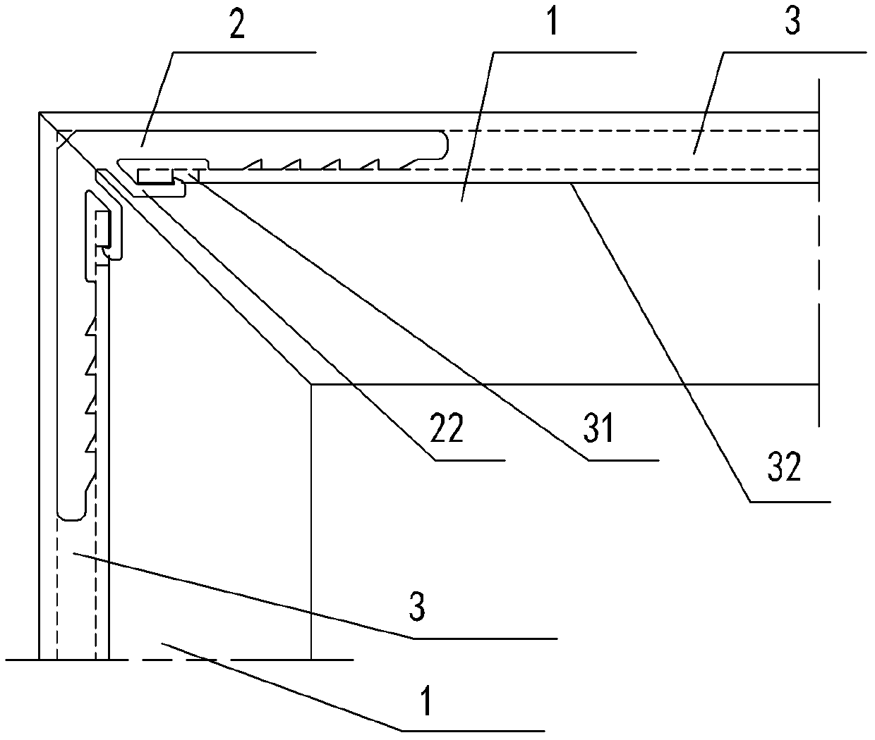
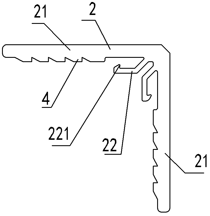
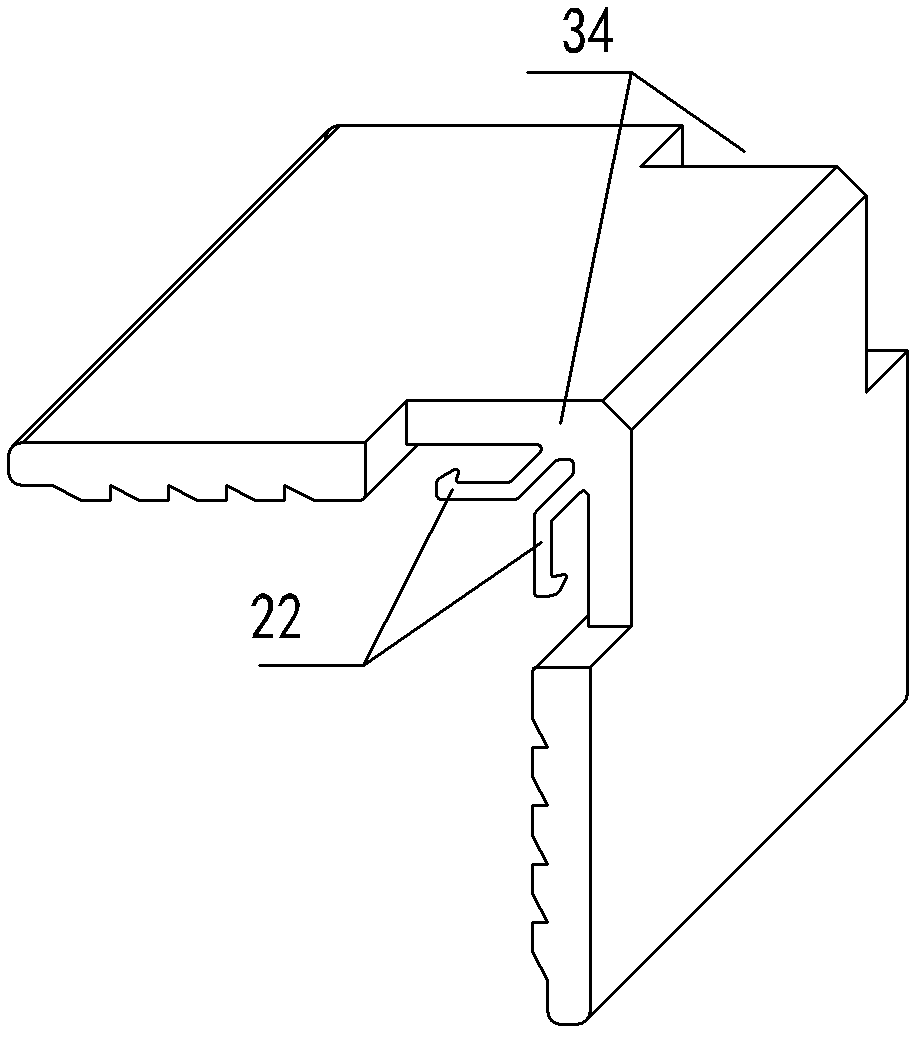
[0025] Such as figure 1 , 2 , 3, 4, 5, and 6, the snap-fit assembly structure of the photovoltaic module includes a component frame 1 and a corner frame 2 assembled with each other. The component frame 1 has a corner frame cavity 3 extending along the length direction. The frame 2 has two intersecting plug-in ends 21 that are respectively inserted into the corner frame cavity 3. The structure of the component frame 1 of the present invention is similar to the riveted assembly structure of the conventional frame corner code. , all of which use the corner code 2 to insert into the corner code cavity 3 of the component frame 1 for positioning and assembly. connected together, and the corner bracket assembly of the present invention only needs to snap the component frame 1 into the corner bracket 2 so that the corner bracket 2 and the frame can be connected together. A slot hole 31 is provided on the side wall 32 of the corner code cavity 3 of the component frame 1 , the side ...
Embodiment 2
[0029] The corner bracket 2 only needs one buckle 22, and the buckle 22 cooperates with the plug-in end 21 on the same side to lock the component frame 1 at one end, and the component frame 1 and the corner bracket 2 at the other end are fixed by riveting. The specific installation process is as follows: Firstly, the corner code 2 is pre-riveted on both ends of the short frame of the photovoltaic module. For the specific structure, see Figure 7 shown. It is only necessary to punch out the card slot hole 31 and the relief gap 33 at both ends of the long frame of the component. The corner bracket 2 and the component frame 1 of this structure are very convenient to manufacture, and the assembly is simpler and more convenient.
Embodiment 3
[0030] This structure can also be adopted for the component frame 1 with an outer cavity. As in Example 3: the component frame 1 with an outer groove cavity, the corner code cavity 3 is in the outer groove of the component frame 1, the corner code 2 can have one or two buckles 22, and the frame with the inner corner code cavity is processed Same, if the end is beveled at an angle of 45°, the punching slot hole 31 needs to be added. The assembly structure is also the same as above. If the single buckle structure is used, screw 5 can also be used to pre-tighten the two ends of the short frame of the photovoltaic module. For the specific structure, see Figure 8 , the assembly of this structure is also simple and convenient. Regarding corner code 2, it can also be designed as Figure 9 and Figure 10 Structure. As in Example 4: Figure 9 Dual snap corner codes shown, with figure 2 Similarly, both the long and short frame of the component need to process the card slot hole...
PUM
 Abstract
Description
Claims
Application Information
 - R&D
- Intellectual Property
- Life Sciences
- Materials
- Tech Scout
- Unparalleled Data Quality
- Higher Quality Content
- 60% Fewer Hallucinations
Browse by: Latest US Patents, China's latest patents, Technical Efficacy Thesaurus, Application Domain, Technology Topic, Popular Technical Reports.
© 2025 PatSnap. All rights reserved.Legal|Privacy policy|Modern Slavery Act Transparency Statement|Sitemap|About US| Contact US: help@patsnap.com


