High-speed taking device for photovoltaic stacked silicon slices

A silicon wafer, high-speed technology, applied in the field of photovoltaic stacked silicon wafer high-speed pick-up device, can solve the problems of cumbersome mechanism and inconvenient use, and achieve the effect of simple structure, simple operation and easy manufacture

Inactive Publication Date: 2012-06-27
ROBOTECHN INTELLIGENT TECH CO LTD
View PDF3 Cites 4 Cited by
  • Summary
  • Abstract
  • Description
  • Claims
  • Application Information

AI Technical Summary

Problems solved by technology

However, this method mechanism is very cumbersome and inconvenient to use.

Method used


Image

  • High-speed taking device for photovoltaic stacked silicon slices
  • High-speed taking device for photovoltaic stacked silicon slices
  • High-speed taking device for photovoltaic stacked silicon slices

Examples


Embodiment Construction

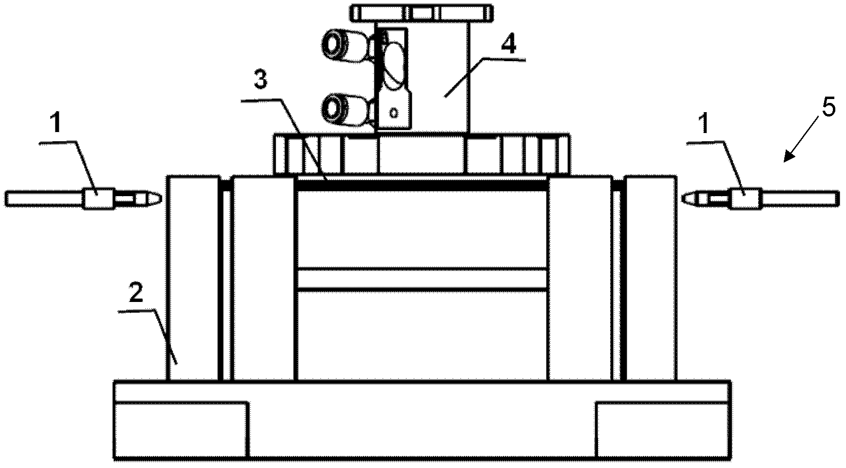
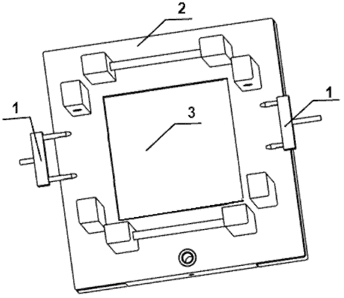
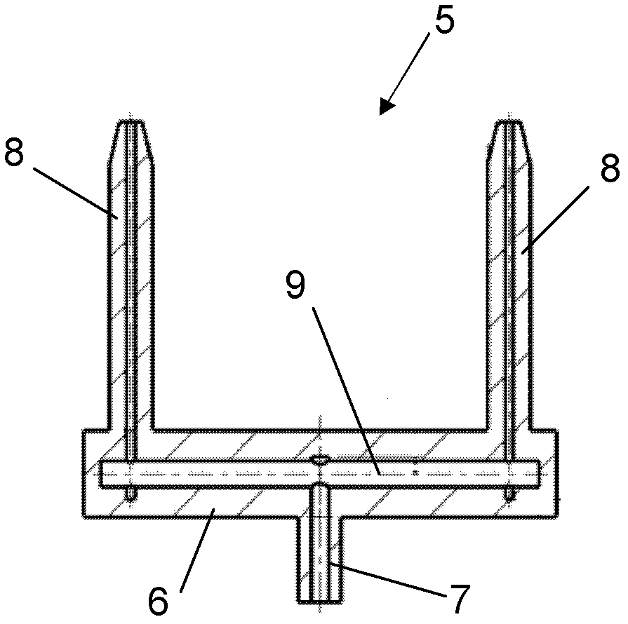
[0019] Such as figure 1 , figure 2 As shown, the photovoltaic stacked silicon wafer high-speed pick-up device of the present invention includes a silicon wafer box 2 with silicon wafers 3 stacked inside, a combined air knife 1 arranged on the side of the silicon wafer box 2, and a combined air knife set above the silicon wafer box 2 The high-speed suction cup 4, the combined air knife 1 includes the opposite-blowing multi-hole air knife 5 symmetrically arranged on both sides of the silicon wafer box 2, and each of the counter-blowing multi-hole air knife 5 has a structure such as image 3 Shown, comprise cutter body 6, be located at the air inlet pipe 7 of cutter body 6 one ends, be located at a plurality of parallel blowing nozzles 8 of cutter body 6 other ends, have in cutter body 6 and have air inlet pipe 7, blowing The mouth 8 is connected with the air duct 9. The number of mouthpieces can be two, three or more, image 3 Shown are two. During use, when the silicon waf...


PUM


Abstract

The invention discloses a high-speed taking device for photovoltaic stacked silicon slices, which comprises a silicon-slice box, a combined wind knife and a high-speed sucking disk, wherein the silicon slices are stacked at the inner part of the silicon-slice box, the combined wind knife is arranged at the lateral part of the silicon-slice box, the high-speed sucking disk is arranged above the silicon-slice box, and the combined wind knife comprises oppositely-blowing porous wind knives which are symmetrically arranged at both sides of the silicon-slice box. Stable and symmetrical lifting forces can be formed by adopting a porous oppositely-blowing structure when the silicon slices are separated, and the uppermost silicon slice can be completely separated from the rest silicon slices without being influenced by the air flow of the sucking disk, slice adhesion is prevented, and the requirement of rapid slice taking is met.

Description

technical field [0001] The invention relates to photovoltaic cell manufacturing equipment, in particular to a high-speed photovoltaic stacked silicon wafer picking device. Background technique [0002] At present, in the process of photovoltaic stacking silicon wafers, there is no problem for low-speed wafer removal by using a single-hole air knife that blows against or a double-hole air knife that blows on one side. However, for high-speed film taking (more than 2000 pieces / hour), the separation effect is not good, and it is easy to cause film sticking. The main reason is that the single-hole air knife for blowing or the air knife for double-hole single-side blowing can form two columnar blowing effects. Although the silicon wafers can be separated to a certain extent, the top silicon wafer cannot be separated from the rest of the silicon wafers. To achieve a truly stable separation, there will be some contact with the underlying silicon wafer. At low speeds, since the su...

Claims


Application Information

Patent Timeline
Patent Type & Authority Applications(China)
IPC IPC(8): H01L31/18H01L21/67
CPCY02P70/50
Inventor 朱绍明戴军
Owner ROBOTECHN INTELLIGENT TECH CO LTD
Why Eureka
Try Eureka