Limit fixing sleeve welding device

A welding device and limit fixing technology, which is applied in welding equipment, resistance welding equipment, metal processing equipment, etc., can solve problems such as low welding efficiency, achieve the effects of reducing low efficiency, reducing production costs, and increasing efficiency

Inactive Publication Date: 2012-07-04
TIANJIN TIANDE SUSPENSION SYST
View PDF7 Cites 4 Cited by
  • Summary
  • Abstract
  • Description
  • Claims
  • Application Information

AI Technical Summary

Problems solved by technology

The original process of this process adopts first pressing to press the limit fixing sleeve into the piston rod, and then spot welding in the spot welding machine, but this welding method can only separate the pressing and welding of the limit fixing sleeve, and the welding efficiency is low

Method used


Image

  • Limit fixing sleeve welding device
  • Limit fixing sleeve welding device
  • Limit fixing sleeve welding device

Examples


Embodiment Construction

[0013] The present invention will be described in detail below in conjunction with the accompanying drawings and specific embodiments.

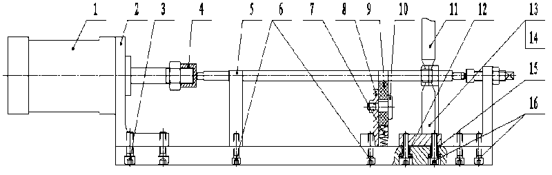
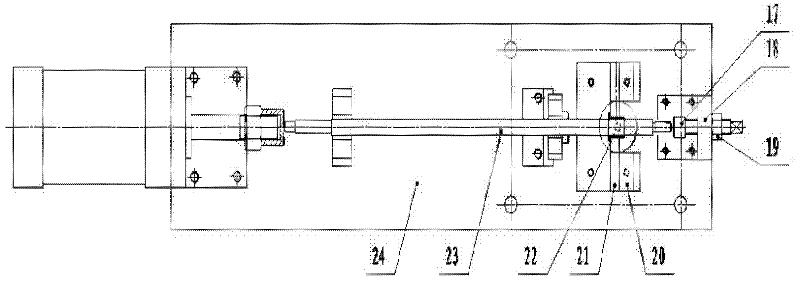
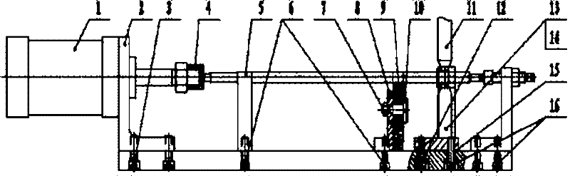
[0014] attached by figure 1 And attached figure 2 It can be seen that the present invention includes a base plate 24, one end of the base plate 24 is provided with a cylinder 1, the cylinder 1 is connected with the base plate 24 through the cylinder bracket 2, the base plate 24 is provided with a bracket I5 and a bracket II8, and the other end of the base plate 24 is provided with an adjusting screw 17, The adjusting screw 17 is connected with the base plate 24 through the limit bracket 18, the base plate 24 is also provided with a positioning bracket 20 and a positioning baffle 21, and the positioning bracket 20 and the positioning baffle 21 are provided with an upper electrode 11 and a lower electrode 13. The positioning bracket 20 and the positioning baffle plate 21 are used for positioning and fixing, 22, and are located on both sides o...


PUM


Abstract

A limit fixing sleeve welding device relates to welding of a piston rod sub-assembly of an automobile shock absorber. A cylinder is mounted at one end of a bottom plate, a limit fixing sleeve positioning device is mounted in the middle of the bottom plate, and an adjusting screw rod is mounted at the other end of the bottom plate and used for limiting a piston rod when a limit fixing sleeve is pressed, so that the size of the limit fixing sleeve is adjusted. The limit fixing sleeve welding device can be used for pressing and welding the limit fixing sleeve, efficiency is increased to a large extent, and cost is reduced.

Description

technical field [0001] The invention relates to the automobile shock absorber production industry, in particular to the welding of the piston rod subassembly of the automobile shock absorber. Background technique [0002] The welding of the limit fixing sleeve of the piston rod sub-assembly is a process in the process flow of the automobile shock absorber. This limit fixing sleeve is used to limit the extension length of the connecting rod of the automobile shock absorber, and its welding strength is directly related to whether it is qualified or not. Safe to use with shock absorbers. The original process of this process adopts first pressing to press the limit fixing sleeve into the piston rod, and then spot welding in the spot welding machine, but this welding method can only separate the pressing and welding of the limit fixing sleeve, and the welding efficiency is low . Contents of the invention [0003] The present invention aims to overcome the deficiencies in the ...

Claims


Application Information

Patent Timeline
Patent Type & Authority Applications(China)
IPC IPC(8): B23K11/11B23K11/36
Inventor 王卫国董利
Owner TIANJIN TIANDE SUSPENSION SYST
Why Eureka
Try Eureka