Clamp for turning irregular sleeve and machining method for same

An irregular, turning technique used in the manufacture of tools, metalworking equipment, metalworking machine parts, etc.

Inactive Publication Date: 2012-07-04
SHANGHAI AEROSPACE EQUIP MFG GENERAL FACTORY
View PDF5 Cites 7 Cited by
  • Summary
  • Abstract
  • Description
  • Claims
  • Application Information

AI Technical Summary

Problems solved by technology

[0003] The purpose of the present invention is to solve the problem of fast clamping and precise positioning of irregular sleev

Method used


Image

  • Clamp for turning irregular sleeve and machining method for same
  • Clamp for turning irregular sleeve and machining method for same
  • Clamp for turning irregular sleeve and machining method for same

Examples


Embodiment Construction

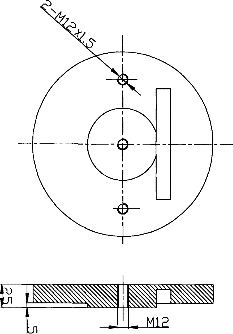
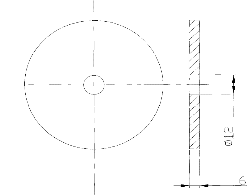
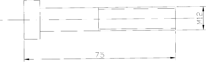
[0013] The specific implementation will be described in detail below in conjunction with the accompanying drawings.

[0014] Such as Figure 1 to Figure 6 As shown, the present invention includes: a reference positioning plate 1, a large washer 2, a screw 3, a double-ended screw 4, a cover plate 5, and a nut 6. Process a cylindrical boss matching the inner hole of the part on the positioning reference plate 1; drill and tap M12 thread in the center; and open a rectangular relief groove above the boss; drill and tap 2-M12×1.5 thread to ensure a certain center distance. When clamping, an inner hole of the part cooperates with the cylindrical boss on the positioning reference plate, and the matching clearance meets the processing requirements of the part. A mounting rib on the part is placed in the relief groove, and the bottom surface of the part fits with the large end surface of the reference positioning plate. , so that the parts can achieve fast and accurate positioning in...


PUM


Abstract

The invention discloses a device for rapidly clamping and precisely positioning an irregular sleeve part. The device comprises a datum positioning plate, a large gasket, a screw, a double-headed screw rod, a cover plate and a nut. The part is attached to a large end face of the datum positioning plate through a boss of the datum positioning plate and the bottom of the part, thereby being precisely positioned, and the part is rapidly clamped by the large gasket, the screw, the double-headed screw rod, the cover plate and the nut. An internal machining element and an external machining element of the part are successfully clamped and turned once, so that turning of the sleeve part is greatly simplified and facilitated. By the aid of the device for turning and clamping the irregular internal sleeve, the part can be rapidly, simply and conveniently mounted on a turning machine tool, conformity of the axis of the part and the axis of a machine tool spindle is ensured, part machining efficiency is greatly improved, and the quality of the part is stable.

Description

technical field [0001] The invention relates to a fixture, in particular to a fixture for turning an irregular sleeve and a processing method thereof. Background technique [0002] At present, sleeve parts are widely used in the design of aerospace products. The sleeve parts are connected to various functional components, and the connection and disconnection of each functional component are performed according to the requirements, so as to realize the transmission of signal information. Due to the high performance requirements of aerospace products, the high precision requirements of parts, and the light weight of the whole product, the design structure of sleeve parts is relatively complicated at present. The design of the overall structure makes this type of part not a simple rotary body, but a corresponding installation rib is added. Such a structure is often not easy to clamp during turning. On the one hand, clamping is difficult, and on the other hand, calibration ofte...

Claims


Application Information

Patent Timeline
IPC IPC(8): B23Q3/00B23P15/00
Inventor 金红星
Owner SHANGHAI AEROSPACE EQUIP MFG GENERAL FACTORY
Why Eureka
Try Eureka