Tool magazine mechanism of central processing machine

A processing machine and tool magazine technology, which is applied to metal processing machinery parts, metal processing equipment, manufacturing tools, etc., can solve the problems of clamping position deviation, increase cost, and spend more time, so as to ensure accuracy and ensure safe effect

Inactive Publication Date: 2012-07-04
昆山北钜机械有限公司
View PDF4 Cites 4 Cited by
  • Summary
  • Abstract
  • Description
  • Claims
  • Application Information

AI Technical Summary

Problems solved by technology

[0005] However, the actual operation situation cannot be as ideal as the above-mentioned treatment. This is because the processing machine is usually adjusted by the manufacturer before the machine tool leaves the factory before shipment. However, after the machine is sold, most of the customers who buy the machine cannot complete such a professional adjustment. Therefore, after the processing machine has been used for a period of time, the error gradually increases and needs to be repaired and adjusted to prevent the clamping part 721 from colliding with the The error of the clamping position between the spindles 71 exceeds the allowable range. At this time, for the customer who purchases the processing machine, it is necessary to suspend work and spend more time to adjust, thus increasing the cost
[0006] In addition, as shown in Figure 11, if the main shaft 71 moves up and retracts the tool, if the timing of its release is slow, the problem of the tool 73 coming out often occurs. The reason is that when the clamping part 721 has clamped When the tool 73 is held but the main shaft 71 continues to move upwards, because the clamp arm 72 relies on the screw head 741 to withstand the inclined section 751 of the stopper 75, thereby blocking the possibility of the clamp arm 72 pivoting upwards again, so that the main shaft 71 will eventually be Bringing the cutter 73 upwards away from the clamping portion 721 also causes the cutter 73 to break away from the clamping of the clamping portion 721, and at this time the main shaft 71 releases the cutter again, thus causing the cutter 73 to throw out and hit the machine tool or the ground at high speed. There is a risk of damage, and in severe cases, it will cause injury to the on-site staff
[0007] The slow release of the above-mentioned main shaft will cause the clamping arm 72 to be pulled by an upward force, so that the screw head 751 will collide with the inclined section 751 of the stopper 75, which will easily cause the clamping portion 721 of the clamping arm 72 to collide with the clamping portion 721 of the clamping arm 72. The clamping position between the main shafts 71 deviates again, so, for the customers who purchase this processing machine, the maintenance cost is also increased

Method used


Image

  • Tool magazine mechanism of central processing machine
  • Tool magazine mechanism of central processing machine
  • Tool magazine mechanism of central processing machine

Examples


Embodiment Construction

[0031] Specific embodiments of the present invention will be further described in detail below.

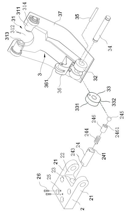
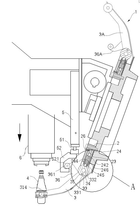
[0032] Such as Figure 1~4 As shown, the central processing machine tool magazine mechanism of the present invention includes:

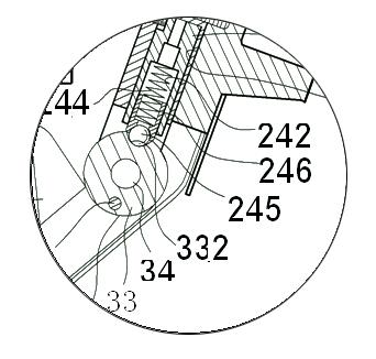
[0033] A rotatable cutter head 1 is provided with a plurality of tool holders 2 around it, and each of the tool holders 2 has two protruding parts 21 protruding outward, and an inner concave part 22 is formed between the two protruding parts 21. The inner wall of the inner recess 22 is provided with an accommodating space 23 recessed into the tool holder 2. A rod body 24 is arranged in the accommodating space 23. One end of the rod body 24 has an opening 241, and the opening 241 There is a chamber 242 which is eccentrically arranged compared with the rod body 24, and the knife clamp seat 2 has two perforations 25 penetrating to the inner side of the chamber 241, and the rod body 24 has a retracted end at the end away from the opening 241 Corresponding ...


PUM


Abstract

The invention discloses an improvement of a tool magazine mechanism of a central processing machine. The tool magazine mechanism comprises a cutter head, a plurality of cutter clamp seats, a plurality of clamp arms and a driving device, wherein the cutter clamp seats are respectively arranged around the cutter head; one end of each clamp arm is pivoted with each cutter clamp seat, and the other end of each clamp arm is used for clamping a cutter; the clamp arms are respectively provided with a locating wheel, and the locating wheels are arranged correspondingly to the cutter clamp seats; the cutter clamp seats are respectively provided with a rod body which is internally provided with an elastic component in a penetrating way; each elastic component leans against a steel ball; and the steel balls lean against the peripheries of the locating wheels. Therefore, the tool magazine mechanism can be used for guiding when the clamp arms rotate and buffering when the cutter is loosened by a spindle, so that the danger that the cutter falls off due to the time difference when the cutter is retracted between the spindle and the clamp arms can be avoided.

Description

technical field [0001] The invention relates to a processing machine, in particular to a tool magazine structure of the processing machine. Background technique [0002] Figure 9 and Figure 10 The picture is a simple schematic diagram of the clamping arm type tool selection rotary mechanism of the tapping center machine commonly used at present, in which the clamping position between the main shaft 71 and the clamping part 721 of the clamping arm 72 is very important, and it is related to the spindle during processing. 71 moves down and grabs one of the keys to whether the tool 73 at the clamping part 721 can be accurately clamped. However, it often happens that the clamp arm 72 cannot be located at the horizontal position as shown in the figure due to inaccurate adjustment. Or there are some errors between the clamping part 721 of the clamp arm 72 and the grasping mechanism (not shown in the figure) of the main shaft 71, so that the above-mentioned grasping action cannot...

Claims


Application Information

Patent Timeline
Patent Type & Authority Applications(China)
IPC IPC(8): B23Q3/155
Inventor 雷春花
Owner 昆山北钜机械有限公司
Why Eureka
Try Eureka