Machine tool

一种机床、旋转轴的技术,应用在金属加工机械零件、维护和安全配件、自动控制装置等方向,能够解决颤振抑制困难、工件成品率下降等问题,达到抑制颤振、实现成品率的效果

Active Publication Date: 2012-07-04
OKUMA CORP +1
View PDF5 Cites 12 Cited by
  • Summary
  • Abstract
  • Description
  • Claims
  • Application Information

AI Technical Summary

Problems solved by technology

[0006] However, conventionally, when the rotational speed of the main shaft is changed periodically, the amplitude and period have to be determined based on the experience of the operator.
In other words, in order to effectively suppress chatter vibration, extensive experience is required, so it is very difficult for inexperienced workers, etc., to suppress chatter vibration, and there are even problems such as a decrease in the yield of workpieces.

Method used


Image

  • Machine tool
  • Machine tool
  • Machine tool

Examples


Embodiment Construction

[0024] Hereinafter, a machine tool according to an embodiment of the present invention will be described in detail with reference to the drawings.

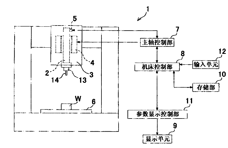
[0025] Reference numeral 1 is a machining center having a main shaft 2 as a rotating shaft to which a tool 14 can be attached via a jig 13, and a motor 4 for rotating the main shaft 2 is built in a headstock 3 which supports the main shaft 2 in a rotatable manner. And an encoder 5 for detecting the rotational speed of the main shaft 2 and the motor 4 . In addition, a table 6 on which the workpiece W is placed is provided at a position facing the headstock 3 .

[0026] On the other hand, reference numeral 7 is a spindle control unit for controlling the rotation speed of the spindle 2 or adjusting the electric power supplied to the motor 4 , and is electrically connected to the motor 4 and the encoder 5 . In addition, reference numeral 8 is a machine tool control unit that controls the overall operation of the machining center 1, a...


PUM


Abstract

In a machine tool which includes a rotary shaft configured to allow a tool or a workpiece to be attached thereto, a driving unit for causing the rotary shaft to rotate is regulated to change a rotation speed of the rotary shaft in such a manner that the rotation speed oscillates with a given amplitude and a given period with respect to a given mean rotation speed, so that chatter vibrations can be suppressed. A parameter display control unit configured to cause a display device to display parameter information related to predetermined parameters for changing at least one of the mean rotation speed, the amplitude and the period is provided so that the parameters can be changed based upon the parameter information displayed in the display device.

Description

technical field [0001] The present invention is a machine tool that performs machining while rotating a tool or a workpiece. Background technique [0002] Conventionally, for example, in a machine tool that cuts the surface of a workpiece by rotating a tool, chatter may occur during machining due to reasons such as low rigidity of the tool. and. As a method of suppressing chattering, for example, as described in Patent Document 1 and Patent Document 2, a method of periodically varying the rotational speed of the main shaft with a predetermined amplitude is known. [0003] prior art literature [0004] Patent Document 1 Japanese Patent Application Laid-Open No. 49-105277 [0005] Patent Document 2 Japanese Patent Laid-Open No. 2000-126991 [0006] However, conventionally, the amplitude and period when the rotational speed of the main shaft is periodically fluctuated have been determined based on the experience of the operator or the like. That is, in order to effectively...

Claims


Application Information

Patent Timeline
Patent Type & Authority Applications(China)
IPC IPC(8): B23Q15/08
CPCB23Q17/12B23Q11/0032B23Q11/0039B23Q15/08Y10T409/304312Y10T409/306832Y10T409/307224
Inventor 西村浩平吉野清石井肇浜口显秀铃木教和社本英二
Owner OKUMA CORP
Why Eureka
Try Eureka