Transmission mechanism

A transmission mechanism and motor vehicle technology, applied in transmission control, transmission parts, movable seats, etc., can solve the problems of enlarged structural space and impact, and achieve the effects of compact structure, reduced manufacturing cost, and small friction

Active Publication Date: 2012-07-04
ROBERT BOSCH GMBH
View PDF6 Cites 3 Cited by
  • Summary
  • Abstract
  • Description
  • Claims
  • Application Information

AI Technical Summary

Problems solved by technology

This also affects other components, especially the output shaft, so that overall the required installation space is larger

Method used


Image

  • Transmission mechanism
  • Transmission mechanism

Examples


Embodiment Construction

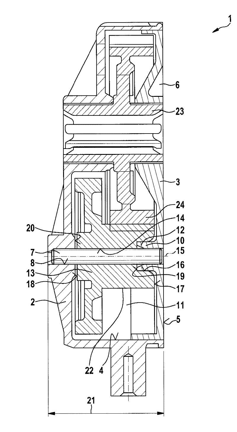
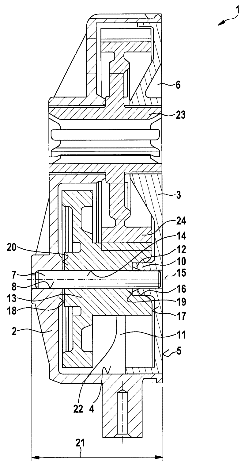
[0014] figure 1 A schematic axial sectional view of a part of a transmission corresponding to an embodiment of the invention is shown. The transmission mechanism 1 is particularly suitable for devices for adjusting motor vehicle seat parts operated by external force. In this case, for example, the adjustment of the seat back can be carried out by means of the transmission 1 via the seat adjustment motor. However, the transmission 1 according to the invention is also suitable for other applications.

[0015] The transmission 1 has a transmission housing part 2 . The housing 2 of the transmission 1 is here formed in the exemplary embodiment by a mechanism housing part 2 . Of course, such a housing can also be composed of a plurality of transmission mechanism housing parts. Furthermore, the gear mechanism 1 has a gear mechanism cover 3 which is inserted into the mechanism housing part 2 at the inner wall 4 of the mechanism housing part 2 . In this case, the gear mechanism co...


PUM


Abstract

A transmission mechanism (1), in particular to a device used for the power-operated adjustment of the seating elements of a motor vehicle, which comprises a housing part (2), a gearbox cover (3), a bearing element (7) connected with one end to the housing part (2) and a first gear (13) rotatably mounted on the bearing element (7). The first gear (13) has an axial recess (16) facing the end face (17) of the gearbox cover (3). The gearbox cover (3) has a bearing dome (10) which extends in the axial recess (16) of the first gear (13). The bearing element (7) is connected with the bearing dome (10) of the gearbox cover (3). Due to the adoption of the above structural design, the thickness of the transmission mechanism (1) can be optimized.

Description

technical field [0001] The invention relates to a transmission mechanism, in particular to a transmission mechanism for a device for operating and adjusting a seat part of a motor vehicle with an external force. In particular, the gear mechanism is suitable for geared motors, which are designed in particular as seat adjustment motors. Background technique [0002] A transmission unit for small motors is known from DE 10 2004 057 227 A1. Wherein, the driving torque output by the motor part is transmitted from the motor shaft to the endless screw rod, furthermore, from the endless screw rod to the helical gear, and the driving torque is output externally by the output shaft rotating together with the helical gear. At the center of rotation, a fixed shaft is now fastened to the transmission housing, which is formed in a hollow and cylindrical mould, which has an opening, one of its end sections being open. The mold of the outer shaft has a covering surface in which the other ...

Claims


Application Information

Patent Timeline
IPC IPC(8): B60N2/02B60N2/22
CPCF16H2057/02082F16H57/031F16H57/021B60N2/4435B60N2/933F16H59/02
Inventor A.迈尔K.多纳特
Owner ROBERT BOSCH GMBH
Why Eureka
Try Eureka